산업용 저항기

. Industrial Resistor
We Seonjinhitech is the original company of the industrial resistors in Korea. Our design, manufacturing, and production technology for resistors boasts the highest level in the domestic industry. In addition, as an EPC company that designs, manufactures, and constructs of all products with our own technology, we have established a customization system that can supply customized products to customers in a timely manner, and continuously develops and supplies new products that are appropriate for the rapid changes in the industry.
◑ Element types of industrial resistor
|
|
|
|
|
V-W grid type (VW)
( 10~50Ω ) |
Edge Wound type (EW)
( 50~100Ω ) |
Heli-Wire type (HW)
( 50~300Ω ) |
|
|
|
|
|
SUS grid type (SG)
( < 10Ω ) |
Wire Wound type (WW)
( for fine resistance ) |
SUS tube type (ST)
( for hi-voltage, hi-power ) |
◑ Supply Procedure (Ex. Load Bank)
◎ Process

◎ Output materials by step
|
Step |
Process |
Activity |
Output |
Remark |
|
1 |
Reception of customer request |
Review of basic requirements received. Confirmation of production and supply conditions |
RFQ data |
|
|
2 |
Basic Specification Design |
Basic configuration and specification design, Customization requirements design |
Draft TDS/TS |
|
|
3 |
System configuration and operation control plan design |
Setup of system operation & control plan, GA design of operation & control panel Basic design of operation & control panel Estimation of required materials (BOM) |
Draft Op’ plan Draft Op’ panel GA Draft control logic Draft BOM |
|
|
4 |
Submit a quote and proposal |
Basic design (BD drawing), Setup of technical specifications, Setup of production and supply conditions, Analysis of purchase and manufacturing cost, Submission of quotation and proposal |
Offer Sheet Proposal Doc. BD drwings TDS/TS |
|
|
5 |
Purchase order review and supply contract |
Review of contract (purchase order) Confirm the supply terms (FOB/CIF/CFR/DAP/DDP) Sign the contract (counter sign) Provide the deviation sheet (if required) |
Contracts (PO) BD drawing TS/TDS BOM |
|
|
6 |
Submission of Approval Documents |
Detailed design Compose of technical specifications (TS) Submission of approval documents |
Approval drawing Technical Data Sheet Technical Spec. |
|
|
7 |
Approval of Design Document |
Reflection of comments on approval doc. Resubmission of revised doc. for re-approval (DCN matters are submitted separately) |
Revised drawings Revised spec. DC Notes |
|
|
8 |
Procurement and production |
Purchase order for manufacturing production |
Required material list up Main parts / sub materials / Accessories Self-made, OEM manufacturing, Self-test PAT |
Separate order for purchasing materials (main parts, sub materials, accessories) Manufacturing/processing sub-assembly (inspection) Medium/large assembly (unit functional test) iTP submission/approval Factory/Shop test report |
|
9 |
Inspection & test |
Submission of ITP Customer witness test & inspection Type test by certified agency (if necessary) |
Additional ITP check Routine Test Report FAT, FAC Type Test Report (if required) |
Customer witness test Test Report Issuance Type test by certified Agency (if necessary) Environment/Durability test Function/Performance Test, Certificate Issuance |
|
10 |
Packing, shipping and delivery |
Ex-works inspection Export packaging (if necessary) Shipping (Domestic, overseas: Import/Export procedures) |
Products Final doc.(Drawing,TS, manual) Packing List, Bill of Lading Certificate of Origin Commercial invoice |
Ex-works inspection sheet (sizing, weighing, Ex-work sheet) Packaging: domestic (Simple), overseas (export packaging) Transportation, Delivery (FOB, CIF, CFR, DAP, DDP) Land / Sea / Air transportation Issue of related Documents (PL, BL, COO, CI.) Delivery, receipt confirmation |

Industrial load resistors (Load Bank Resistors) are equipment that generate artificial loads (power consumption) for performance testing of electrical equipment, generators, UPS, etc. Those are operated like an actual loads by consuming power as heat and are used for inspection, maintenance, and test runs of equipment. In particular, they are equipment that must be installed in places where emergency power is essential, such as factories, hospitals, and data centers, to ensure the stability of the power system. The resistor elements are mainly made of Ni-chrome or iron chrome that can withstand high-power and high-temperature environments, and are made into wire or flat shapes.
|
|
|
|
Out door type LDR |
Indoor type LDR |
◑ Featutres
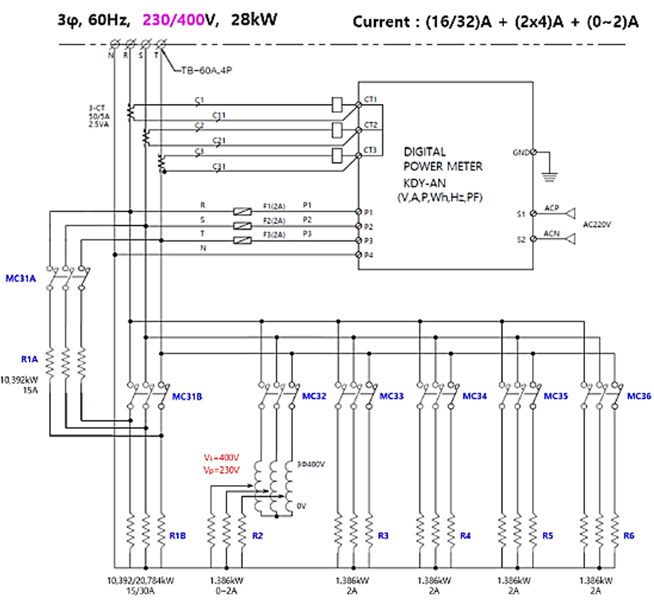
◑ Basic Circuit Drawing
◑ Enclosure

◑ Selection of LDR Specification


Neutral grounding resistor (NGR) is a resistor used to ground the neutral point of a transformer or generator. It is used to limit the fault current flowing when a ground fault occurs in a three-phase power system to a specified value or less, which plays an important role in reducing damage to electrical equipment and the risk of fire. NGR is mainly used in high-voltage systems and performs detection, blocking functions simultaneously by linking with a protection relay. It is usually manufactured in a coiled form using a metal wire that is resistant to high heat, & in the case of large-capacity, low-resistance, it is manufactured in a grid form by cutting SUS plate. The housing is designed and manufactured for indoor use, outdoor use, and waterproof/dust-proof structure depending on the installation conditions.

◑ NGR Out Look
|
|
|
|
Outdoor type NGR |
indoor type NGR |
◑ Effects of NGR installation
√ Prevents insulation breakdown of equipment and lines due to abnormal voltage in case of a single-line ground fault
(reduces insulation level of lines and related equipment)
√ Prevents linked accidents by temporarily blocking abnormal over voltage
√ Restricts the level of potential hazardous fault current
√ Ensures safety for related systems (GEN, TR, Motor, etc.) and personnel
√ Reduces arc exposure and generates alarms in case of a ground fault
√ Provides optional ground fault detection tripping level
√ Detects fault circuits and measures fault currents using CT and ground fault protection relay (OCGR)
√ Function to suppress inductive faults in communication lines in case of a ground fault
√ Prevents sudden changes in load in case of a generator ground fault
◑ Types of neutral grounding way
|
none grounded type |
directly grounded type |
Resistance grounding type |
Reactor grounding type |
|
|
|
|
|
|
|
|
Zn= ∞ No grounding wire Applicable to general distribution sys. (~3.3kV, 6.6kV) Maintains high impedance to the neutral point Small ground fault current allows transmission even in the event of momentary ground fault Less inductive interference in communication lines Ground fault relay malfunctions frequently Can be operated as V-connection when 1 line is faulted in Δ-connection. |
Zn=0 Direct grounding with conductor Applicable to ultra-high voltage (>15kV) systems Almost no voltage increase in the healthy state, Protective relay operation is reliable Reduction of insulation level of related equipment, Large inductive interference in communication lines Very large fault current in case of ground fault |
Zn=R High resistance: >100~1000Ω(5~100A) Low resistance: <30Ω (>200A) Restricts fault current to a specified value or less. The resistance value is selected so that the ground voltage of the healthy part does not exceed 1.3 times the normal voltage in the event of a single line ground fault. If the resistance is too large, the relay operation becomes difficult and the ground voltage of the healthy part increases. |
Zn= jXL Applied to medium-distance transmission lines (66kV) Initial fault current protection function. Applied with L value that can resonate in parallel with the line ground electrostatic capacitance. Power transmission is possible even in the event of a ground fault. Less inductive interference on communication lines. Stability Excellent, but maximum abnormal voltage in case of a fault. Low reliability of protective relay operation |
|
◑ NGR configuration according to transformer wiring
|
in case of the transformer secondary is Y-connected |
in case of the transformer secondary is Y-connected |
||
|
Install NGR directly on the neutral point of the secondary side of the transformer, Install CT, DS, relay (51N) as needed to improve safety protection and operability. |
Use a grounding transformer (GTR) for grounding on the secondary side of TR and connect the NGR to its neutral point. Since GTR operates only in the event of a fault such as a ground fault, it is usually designed with a short-time rating. |
||
|
TR 2'ry neutral point grounding |
TR 2'ry open type, Δ -TR grounding |
Zig-Zag TR neutral point grounding |
Generator neutral point grounding |
|
|
|
|
|
◑ NGR Protection Circuit
Generally, the NGR value is set so that the ground fault current is limited to 5~100 (high resistance) and 200-300A (low resistance) in the case of a 1-line ground fault. The ground fault current is detected by the ground over current relay 51N, and the NGR is protected by displaying an alarm and tripping the circuit breaker on the power side when the time is less than the rated time of the NGR.
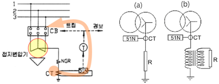
< Configuration of NGR Protection circuit >
◑ NGR Configuration (Application Cases)
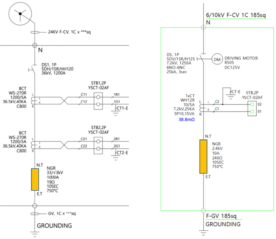
< Remote monitoring & manual control NGR > < Electric drive type remote control NGR >
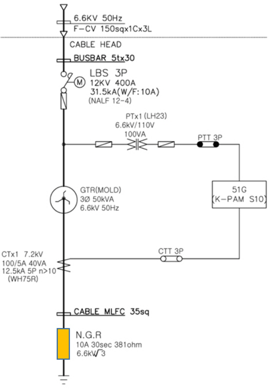
< Self-controlled NGR by self-GTR and relay >
◑ Basic Structure of NGR
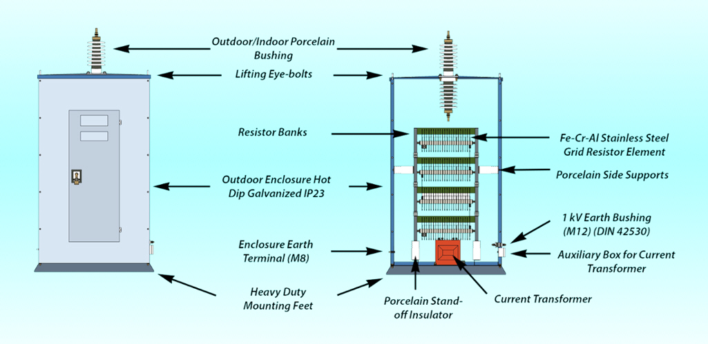
◑ Selection of NGR Spec.
◎ Considerations when selecting the NGR Spec.
√ Line-to-line voltage (VL) or phase-to-phase voltage (Vs) of the main transformer
√ Continuous operating time and maximum current criteria
√ Short-time rating check: Typically applied for 10 seconds, 30 seconds or 60 seconds
√ Continuous rating check: Typically applied at 5% to 10% of full load current
√ Maximum current that can flow in cold condition
√ Insulation class specified based on line-to-line voltage
√ Refer to the maximum short-time temperature rise of the resistor as 760°C according to IEEE Std 32-1972
(Requirements for Neutral Grounding Resistance)
√ Check the protection IP rating for outdoor or indoor enclosure: Standard enclosure applies IP10, IP13 or IP23
√ Enclosure material can be mild steel, powder coated finish or hot-dip galvanized, stainless steel
√ Whether auxiliary items CT, VT, DS, GTR or other options are applied
◎ Selection of NGR Spec.

※ Calculation of NGR resistance : Rg = (Line V÷√3)÷Rated Current
Ex.> When Line VL : 6600V, Rate current IR : 100A
Then NGR resistance Rg will be calculated as bellow ;
∴ Rg = (6600/√3)/100 = 38.1 Ω
◎ NGR Usage Time Rating
√ It refers to the time it takes for the surface temperature of the resistance element to rise to the rated allowable temperature,
√ It is stable for the system equipment to set it slightly longer than the ground fault detection and interruption device of the power line.
√ Short-time rating is generally used as 10 sec, 30 sec, 60 sec, <10 min for the ground fault current flowing to the neutral point,
√ Duration rating is set to an average of >10 min.
◎ Temperature rise limit of NGR
|
Rated Using time |
temperature rise limited |
Standard |
Remark |
|
Short time rate (<10min) |
760°C |
IEEE 32(1972) |
|
|
Short time rate (<10min) |
750°C |
KISC |
국 내 기 준 |
|
Delay time rate (Average 10min) |
610°C |
IEEE 32(1972) |
|
|
Delay time (Average 10min) |
450°C |
KISC |
국 내 기 준 |
|
Continuous time rate |
385°C |
IEEE 32(1972) |
|
|
Continuous time rate |
350°C |
KISC |
국 내 기 준 |
◎ Rated current and appearance spec. by voltage
정격전압 (kV) | 정격전류 (A) | 정격사용시간 (sec) | 온도상승한도 (℃) | width (mm) | Depth (mm) | Height (mm) |
3.3 /√3 | 100 | 10 / 30 | 350 / 750 | 600 | 445 | 630 |
200 | 10 / 30 | 350 / 750 | 600 | 445 | 630 | |
400 | 10 / 30 | 350 / 750 | 600 | 625 | 870 | |
6.6 / | 100 | 10 / 30 | 350 / 750 | 600 | 535 | 630 |
200 | 10 / 30 | 350 / 750 | 600 | 625 | 950 | |
400 | 10 / 30 | 350 / 750 | 600 | 715 | 1190 | |
11.6 / | 100 | 10 / 30 | 350 / 750 | 705 | 800 | 1200 |
200 | 10 / 30 | 350 / 750 | 705 | 900 | 1200 | |
400 | 10 / 30 | 350 / 750 | 705 | 900 | 1560 | |
22.9 / | 100 | 10 / 30 | 350 / 750 | 705 | 1020 | 1560 |
200 | 10 / 30 | 350 / 750 | 705 | 900 | 1920 | |
400 | 10 / 30 | 350 / 750 | 705 | 1400 | 1920 |
◎ Calculation of GTR capacity (Real case)
( According to Westinghouse Data )
1) 3phase Equivalent Power Capacity, Equivalant power (kVA)
Pa = V / √3 * Ig * Kf
V : Line Voltage (kV)
Ig : Earthing Current (A)
K : Factor (%), (NPCCR - Neutral Point Continuous Current Ratio to ground fault current)
2) K Factor
|
Duration (time rate) |
Ratio of neutral point continuous current to ground fault current (%) |
||||
|
0~5% |
10% |
15% |
20% |
25% |
|
|
< 10 sec |
0.11 |
0.11 |
0.157 |
0.206 |
0.264 |
|
~ 1 min |
0.112 |
0.141 |
0.18 |
0.223 |
0.269 |
|
~ 10 min |
0.206 |
0.233 |
0.26 |
0.283 |
0.32 |
|
> 10 min |
0.602 |
0.608 |
0.619 |
0.633 |
0.65 |
3) Calculation of GTR Power Capacity (Example)
☞. Condition of NGR Specification
Rate Voltage - V : 6.6 / √3 kVA
Earthing Current - Ig : 100 A
Resistance - R : 38.1 Ω
Duration time : 30 sec ( < 1 min )
K Factor : 0.269 at 30 sec, and 25% of NPCC ratio (harsh condition)
☞. Calculation of GTR Capacity
Equivalent Capacity Pa (kVA)
= V / √3 * Ig * Kf
= 6.6 / 1.732 * 100 *0.269
= 102.5 kVA
∴ Required a 100 kVA GTR
◑ NGR test and Evaluation
|
No |
Test class. |
Detailed test item |
Evaluation Criteria |
|
1 |
Regular test & inspection |
Measuring insulation resistance between housing and resistor Measuring DC resistance of resistor Measuring thickness of zinc plating or paint Testing insulation of resistor block
|
|
|
2 |
Durability test |
Temperature rise test Protection class impulse and withstand voltage test |
(1.2 / 50 µs) |
|
3 |
Special Test (if necessary) |
Resistor AC Resistance Measurement Insulation Resistance Test (Megger) Seismic Test
|
|
|
4 |
Optional details |
System voltage (kV) Line-neutral voltage (kV) Required rated current (A) Required resistance value (Ω) Maximum ON time (sec) and duty cycle Bushing inlet or cable inlet specifications Current transformer rating (if applicable) Disconnector switch (if applicable) type Special options (if applicable) |
|

High resistance grounding devices are used to prevent loss and casualties due to sudden power outages, fires, etc., while maintaining momentary over voltage protection of the grounding system. It complements the shortcomings of the existing non-grounding method and direct grounding method, and prevents damage and confusion caused by power outages due to ground fault accidents by keeping ground fault current at a minimum of several mA to several tens of mA and allowing continuous operation. In other words, when a ground fault accident occurs, an alarm sounds to notify the occurrence of a fall, while keeping ground fault current at a minimum so that the fault point can be found and repaired. HRG is effective in preventing fire and arc accidents, and is mainly used in places where power outages are fatal, such as industrial plants, data centers, and military facilities. It is always configured with a protective relay to ensure high insulation and stability.
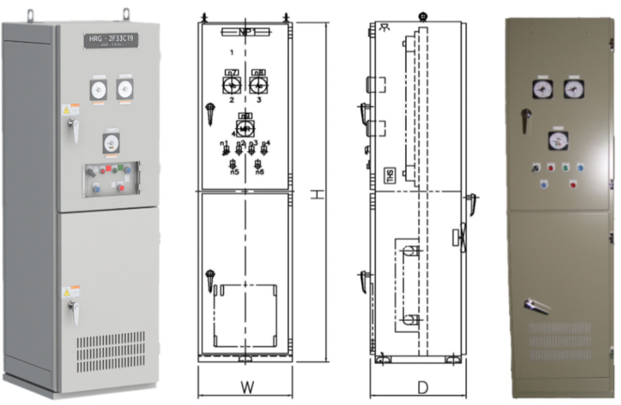
< Exterior appearance of High Resistance Grounding Equipment(HRG) >
* It can detect a current leak in advance, allowing preventive maintenance.
* It can prevent a power outage for the entire system even in the event of a complete ground fault, and the exact fault point can be found
through a current detector.
* It can suppress temporary over voltage even in the event of a ground fault that generates an arc.
* The system can continue to operate even in the event of a single-line ground fault.
* It can identify the exact fault point by pulsing the ground fault current.
* It can be installed in various ways depending on the installation conditions.

◑ HRG Grounding Methods
|
Y-connection circuit grounding method using a high resistance
|
Grounding method of Δ-connection circuit using Zig-Zag TR |
Grounding method of Δ-connection circuit using GTR |
|
Install a high resistance HRG between the secondary neutral point of the main transformer and the ground. |
In case the secondary side of the main transformer is a Δ connection without a neutral point, install a Zig-Zag TR for grounding and install an HRG between the neutral point and the ground. |
In case the secondary side of the main transformer is a Δ connection without a neutral point, install a Zig-Zag TR for grounding and install an HRG between the neutral point and the ground. |
|
|
|
|
◑ HRG Basic Configuration (Example)
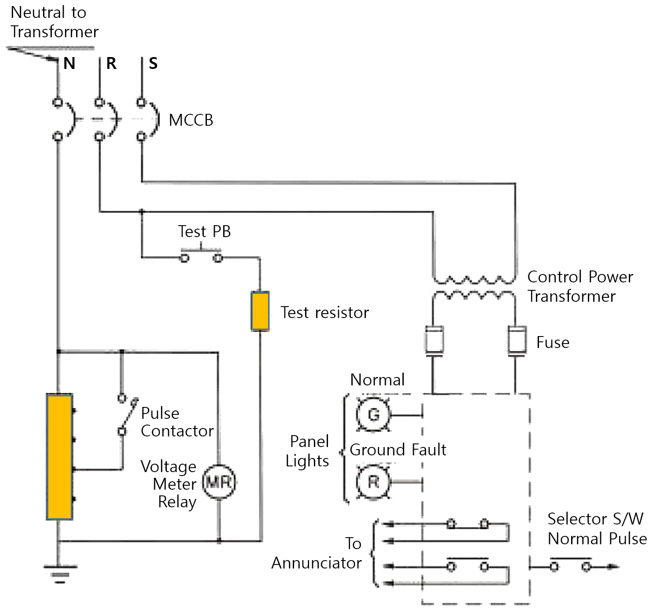
< HRG configuration with local test function >
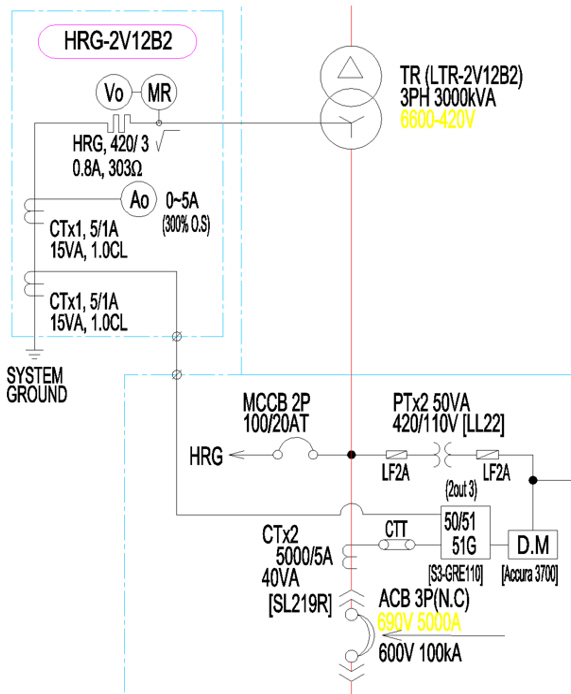
< HRG configuration diagram with remote monitoring and control function >
◑ Selection of HRG Spec.
◎ Differences between NGR and HRG ?
① Main purpose of using a neutral grounding resistor ?
It protects the transformer and line by limiting the ground fault current flowing to the neutral point of the transformer in the event of a ground
fault on the first line.
② Difference between NGR and HRG ?
In the case where the fault current can be cut off by turning off the main circuit breaker (CB) in the event of a ground fault, respond with
a low-resistance NGR, and in the case where the main circuit breaker must not be turned off in the event of a ground fault and the operation
must be continued, respond with a high-resistance HRG..
◈ Low resistance grounding NGR
Used for short-time rating: 10~30 seconds)
Ground fault occurs → Relay operates → CB operates (load cutoff)
◈ High resistance grounding HRG
Used for continuous rating: 10 minutes or longer,
Ground fault occurs → Relay operates → Alarm occurs (Can track ground fault point by pulsing)
The reason why the resistance value is large and the current value is small in continuous rating is to reduce the load capacity (kW).
◎ Calculation of HRG Resistance (Example)
The HRG resistor capacity based on a 460V transformer is calculated as follows:
☞. Resistance value when applying 100A : R100 = (460V ÷ √3) ÷ 100A
= 266V ÷ 100A
= 2.66 Ω
Capacity when used continuously at 100A : P100 = 100A x 100A x 2.66Ω
= 26,600 W
Here, the 26.6kW resistor is a fairly large capacity and must be applied while considering both heat generation and cooling.
☞. Resistance value when 1A is applied : R1 = (460V ÷ √3) ÷ 1A
= 266V ÷ 1A
= 266 Ω
Capacity when used continuously at 1A : P1 = 1A x 1A x 266Ω
= 266 W
Here, the 266W resistance is the capacity of the space heater used in the panel, so continuous use is possible, and HRG generally
applies 1A or less.
◎ Selection of HRG Spec.


Crane resistors are connected to the secondary side of wound induction motors used in cranes to limit the starting current of the motor, control the speed, and perform braking when driving the crane. They are mainly used in wound induction motors or DC motors, and have the function of controlling the current or consuming regenerative power according to the load conditions during operation. Depending on the purpose and control method, the speed and torque values of the crane motor to which the crane resistor is applied vary greatly.
|
|
|
|
Indoor type CCR |
Outdoor type CCR |
◑ Selection of CCR Spec.
◎ Selection of CCR Spec.

◎ Selection of CCR Frame size

◎ Selection of Outdoor type CCR Frame size

◎ 크레인 제어방식 별 토오크 제어 범위
|
Purpose |
Control method |
Control Torque |
Maneuver Torque |
|
Hoist |
2'ry Resistance control |
3, 4, 5 |
100 % |
|
S (S.C Brake control) |
4, 5, 6 |
Winding down 50 % |
|
|
Winding up 135 % |
|||
|
E (E.C Brake control) |
4, 5, 6 |
Winding down 35 % |
|
|
Winding up 135 % |
|||
|
D (Dynamic W) |
3, 4, 5 |
Winding down 50 % |
|
|
Winding up 120 % |
|||
|
T (Thyristor control) |
3, 4, 5 |
Winding down 40 % |
|
|
Winding up 200 % |
|||
|
C (direct control) |
5, 6, 7 |
100 % |
|
|
Travelling Traversing |
2'ry Resistance control |
3, 4, 5 |
50 % |
|
P (Plugging control) |
4, 5, 6 |
Stopping 40 % |
|
|
T (Thyristor control) |
3, 4, 5 |
Winding up 50 % |
|
|
100 % |
|||
|
C (direct control) |
5, 6, 7 |
50 % |

|
|
|
|
Resistor for motor starting (Vertical cooling type) |
Resistor for motor starting (side cooling type) |
◑ Features by STR type
1) Metal MC-type starting resistor
The method of using an electronic contactor to short-circuit the resistor section is simple in structure and easy to maintain, making it economical.
2) Metal CAM-type starting resistor
The method of using a mechanical CAM to short-circuit the resistor section, allowing manual starting and stopping.
3) Liquid-type starting resistor
√ No sparks occur because the electrode is inserted into the electrolyte and operates.
√ The resistance can be varied infinitely, so the motor can be started/stopped smoothly.
√ A cooling device is required for speed control because a lot of heat is generated.


< Basic circuit diagram of a motor starting resistor >

When using an inverter for motor control, the physical inertial energy generated from the motor's rotational axis during deceleration or stop during operation is absorbed by the inverter. This causes the DC bank voltage of the inverter to rise, which may damage power capacitors or semiconductor devices. To prevent this phenomenon, a braking resistor for the inverter is a device used to absorb and dissipate the energy regenerated in the inverter.
|
|
|
|
Outdoor type DBR appearance |
indoor type DBR appearance |
◑ DBR Dynamic characteristics
DBR works as a brake function that rapidly reduces the rotation speed of the motor in the process of exhausting the regenerative energy of the motor, which significantly shortens the time it takes for the motor to stop, and when you look at the process, you can see the following dynamic characteristics.

< Dynamic characteristics curve of DBR >
◑ DBR Products Features
The DBR products supplied by our company are manufactured based on customized designs that reflect various customer requirements.
√ Wide range of basic model selections through the establishment of various model series
√ Standardization of design and manufacturing process ensures the shortest delivery time
√ Easy to install in panels due to small size and light weight
√ Large overload capacity and excellent cost-effectiveness
√ Manufacturing based on customized designs according to customer requirements
√ Special purpose new product development service

◑ DBR Location in the inverter system
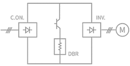
< DBR Application Circuit >

< Configuration of motor control system with DBR >
◑ Selection of DBR Spec.
Since DBR specifications are determined based on the target motor's capacity and usage conditions, detailed specifications and specifications are decided through discussion during the customization design stage.
1) Selection of DBR Spec.

2) Enclosure type and appearance
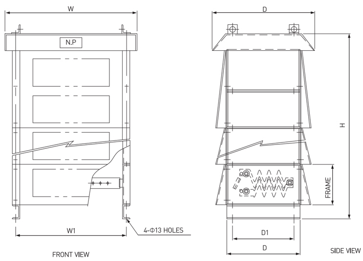


If power conversion devices are used a lot in a certain area, voltage waveform distortion and harmonic currents are generated accordingly, which causes temperature rises in various devices and a lot of related noise. This causes malfunctions in various devices or information and communication failures. Harmonic filter resistors are devices applied to prevent these negative phenomena and are composed of a combination of RLC devices.
|
|
|
|
|
Indoor type HFR (1/2) |
indoor type HFR (2/2) |
Outdoor type HFR |
◐ HFR Products Features
Resistors for harmonic filters supplied by we Seonjinhitech Co. Ltd. are manufactured as high-voltage non-inductive resistors considering the filtering performance.
◐ HFR Basic Circuit
|
|
|
|
|
High frequencies pass filter |
Low frequencies pass filter |
|

Coil resistors are wound with ribbon wires and have excellent heat dissipation effects when subjected to load, making them suitable as main resistors for high-power load resistors, braking resistors, welding machine loads, inverter loads, etc.
|
|
|
|||
|
Wound resistor circuit |
권선형 저항기 셀 |
|||
◐ EWR Features
It is composed of ceramic with excellent insulation and heat resistance and a coil resistor with precise and stable resistance characteristics.
◐ Capacity & resistance characteristics by EWR types
|
Model |
Power consumption |
resistance range |
Resistance tolerance |
Size (mm) |
|||
|
with Fan in free air |
EWS |
EWF |
L1 |
L2 |
|||
|
EWS / EWF400 |
600 W |
400 W |
0.02 ~ 0.25 |
0.26 ~ 3.3 |
5 % (j) 10 % (k) |
240 |
205 |
|
EWS / EWF600 |
600 W |
600 W |
0.029 ~ 0.28 |
0.39 ~ 4.95 |
310 |
275 |
|
|
EWS / EWF800 |
1.3 kW |
800 W |
0.039 ~ 0.5 |
0.51 ~ 6.6 |
380 |
345 |
|
|
EWS / EWF1000 |
1.3 kW |
1.0 kW |
0.051 ~ 0.63 |
0.64 ~ 8.2 |
450 |
415 |
|
|
EWS / EWF1200 |
1.3 kW |
1.2 kW |
0.061 ~ 0.75 |
0.76 ~ 9.9 |
520 |
485 |
|
|
EWS / EWF1400 |
1.3 kW |
1.4 kW |
0.071 ~ 0.88 |
0.89 ~ 11.5 |
590 |
555 |
|
|
EWS / EWF1600 |
1.3 kW |
1.6 kW |
0.081 ~ 1.0 |
1.10 ~ 13.2 |
660 |
625 |
|

********************************************************************************************************************************************************************************
(주)선진하이텍 / Seonjinhitech Co., Ltd.
경기도 화성시 향남읍 발안공단로 4길13 / 대표 : 백용호
18623, 13 Balangongdan-ro 4-gil, Hyangnam-eup, Hwaseong-si,
Gyeonggi-do, Republic of Korea
Tel : +82-31-8059-1387 / Fax: +82-31-8059-1397
E-Mail : sjhtech@seonjinhitech.co.kr
Website : http://seonjinhitech.co.kr


