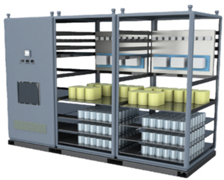
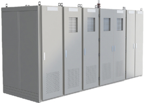
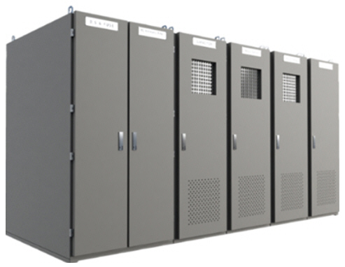
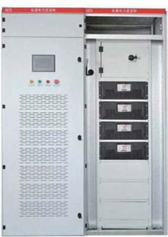
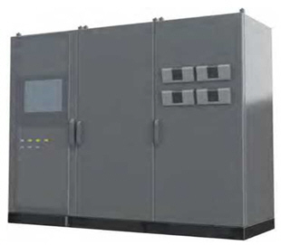
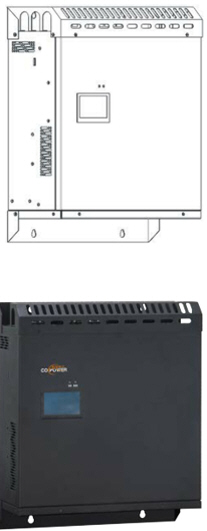
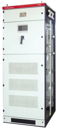
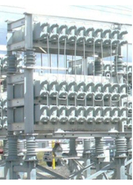
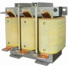
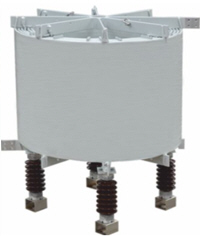
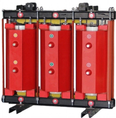
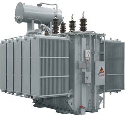
전력품질개선설비

Power Quality Improvement System
When a large amount of nonlinear uneven load is applied to the power system, various types of abnormal voltages and harmonic currents are generated, which significantly deteriorate the power quality of the system, such as lowering the power factor and distorting the voltage waveform. This causes various adverse effects on related equipment, such as output reduction, malfunction, overheating, and vibration. Equipment that reduces or eliminates these damage phenomena below the standard level is called power quality improvement equipment.
◑ Causes of abnormal voltage and harmonic generation
Harmonics are generated by nonlinear loads such as rectifiers, power control equipment, arc furnaces, and welders, and these nonlinear loads are interpreted as sources of harmonic generation in power circuits. The main sources of generation are as follows:
√ Chopping current of power conversion devices such as converters and inverters
√ Excitation current for inductors such as transformers and motors
√ Transient current of electric furnaces, arc furnaces, etc.
√ Corona current of transmission lines
√ Load current of electric welders
◑ Harmonic Characteristics and Problems
Harmonics generated from nonlinear loads are synthesized from odd harmonics of various orders, as shown below.

< Harmonic waveform structure by order >
Harmonic currents are distributed and flow according to the impedance size of the power circuit, causing the following various harmful effects:
√ Malfunction of adjacent electrical and electronic components
√ Overheating of upper-level transformers and neutral lines
√ Malfunction of power factor compensation capacitors
√ Causing power generation and transmission and distribution losses
√ Causing disruption and interruption of protection control and communication networks
√ Causing additional losses due to overheating losses in distribution panels, cables, motors, etc.
√ Increased electrical and mechanical stress on the electrical system
√ Incurring enormous operating losses and replacement costs when related equipment malfunctions or fails early, resulting in shutdowns
√ Shortening the lifespan of various load facilities including power system facilities
√ Early deterioration of power equipment insulation

< Harmonic current generation and its impact on load circuits >
◑ Classification of power quality improvement equipment
The power quality improvement facilities commonly used in power systems and industrial sites are summarized below.
|
No. |
Areas for improvement |
Equipment |
Main Function |
|
1 |
THD restriction |
Passive Harmonic Filter (PHF) |
LC filter designed to remove only specific harmonics. Simple structure and cheap, but lacking in flexibility |
|
2 |
Overvoltage suppression filter (TVSF) |
Suppressing abnormal voltage at start/stop of large impedance load |
|
|
3 |
Sine wave Filter (SWF) |
Converting square wave voltage of power electronic device output to sine wave |
|
|
4 |
HG-Matrix Low Pass Filter (M-LPF) |
Removing harmonics by generating and superimposing low-pass inverse harmonics |
|
|
5 |
Active Power Filter (APF) |
Analyzes various harmonics in real time and then add the offset current. Suitable for places with many nonlinear loads and has high precision. |
|
|
6 |
Reactive power compensation |
Static Var Compensator (SVC) |
R-L-C, Thyristor-based constant voltage maintenance and flicker suppression function, Suitable for removing flicker sources in large-scale industrial sites, welding machines, etc. |
|
7 |
Static Var Generator (SVG) |
High-speed IGBT-based, reverse current injection, compensates f or reactive power to maintain constant voltage and frequency faster and more precisely than SVC
|
|
|
8 |
Capacitor Bank (C-Bank) |
Power factor improvement through lead reactive current compensation. Simple and low cost, but difficult to control precisely.
|
|
|
9 |
Reactor Bank (L-Bank) |
Power factor improvement through leg reactive current compensation. Simple and low cost, but difficult to control precisely.
|
|
|
10 |
Compensation of Voltage fluctuation & flicker |
Automatic Voltage Regulator (AVR) |
Automatically maintains a constant volts when the voltage is high or low. Effective for protecting precision devices or communication equipment. |
|
11 |
Response to Short-time power outage |
Uninterruptible Power Supply (UPS) |
Emergency power supply that supplies power immediately in the event of a power outage. Protects sensitive equipment such as servers and medical devices. |
|
12 |
Response to long-term power outage |
Energy Storage System (ESS) |
Responding to power outages and load fluctuations with a large-scale power storage system. Useful when linking with renewable energy sources such as solar and wind power. |
|
13 |
Protection of surge and overvoltage |
SPD (Surge Protection Device) |
Absorbs lightning or abnormal voltage to protect equipment Essential for protecting distribution panels, communication equipment, and IT devices |
|
14 |
ISTR (Isolation Transformer) |
Noise and surge protection, grounding problem improvement Suitable for sensitive electronic equipment |
◑ Measures of Harmonics Protection
Following methods are commonly used to prevent harmonics in the power system or industrial facilities.
√ Increase the pulse number of the power conversion device.
√ Install a harmonic filter device to eliminate it.
√ Install a series reactor on the power capacitor.
√ Use a double conductor or multi-conductor to prevent corona in the line.
√ Eliminate harmonics by connecting the transformer with a delta connection.
√ Secure sufficient separation distance from the harmonic generator and use shielded cables.
√ Separate the ground from the harmonic generator.

The most economical way to remove harmonics is the passive harmonic filter. The passive harmonic filter is physically installed in parallel with the
harmonic-generating load at a location adjacent to the harmonic-generating load. In this way, the harmonic current generated from the nonlinear load
can be absorbed by the passive harmonic filter, and the harmonics that leak into the power system (unabsorbed portion) can be minimized. A fairly large
capacitor is applied to the passive harmonic filter, and a capacity corresponding to the reactive power of the lagging component (reactor) that is usually
generated is required.
◑ PHF Appearance
|
|
|
|
PHF internal arrangement |
PHF External Appearance |
◑ Principle of Harmonic Filter
A low-pass filter is a filter that passes low-frequency signals and blocks or impedes the flow of high-frequency signals. It can be configured by combining a capacitor (C) or an inductor (L) with a resistor (R). A low-pass filter composed of a resistor (R) and a capacitor (C) is called a low-pass RC filter, and a low-pass filter with a resistor (R) and an inductor (L) is called a low-pass RL filter.

< PHF low pass filter behavior >
◎ Low Pass RC Filter
A low-pass RC filter is a filter circuit consisting of a resistor and a capacitor that passes low-frequency signals and blocks high-frequency signals. To configure a low-pass RC filter, place the resistor in series with the input circuit and place the capacitor in parallel with the input circuit, as shown in the figure below.
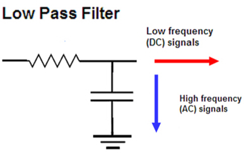
< PHF Low pass RC Filter >
In the above circuit, the capacitor is a reactive element, so it has different resistance characteristics for signals of various frequencies coming through it. The capacitor is a reactive element that shows very high resistance to low frequency or DC signals, and provides low resistance to high frequency signals. In the above circuit, the DC component is blocked by the capacitor and flows to the terminal in the direction of the arrow on the right, and the high frequency signal passes through the capacitor because the capacitor provides very low resistance.
◎ Low Pass RL Filter
A low-pass RL filter is a filter circuit consisting of a resistor and an inductor, which passes low-frequency components and blocks high-frequency components. The low-pass filter places the inductor in series with the input circuit, and the resistor in parallel with the input circuit, as shown below.

< PHF Low pass RL Filter >
The operating principle is based on the characteristics of inductive reactance, and the size of the inductive reactance is determined by the frequency of the current passing through the inductor. However, unlike capacitors, inductors have very high resistance to high-frequency signals and very low resistance to low-frequency signals. Therefore, they show characteristics that are the opposite of capacitors, and the positions of the resistors in the RC and RL filter circuits are switched to each other. Therefore, based on this, the above RL circuit effectively operates as a low-pass filter, because high-frequency components are blocked from entering and low-frequency components pass through without being hindered.
◑ Operation concept of passive harmonic filter

< Operation concept of passive harmonic filter >
◑ Types of passive harmonic filters

< Types of passive harmonic filters >
◑ Main Function of passive harmonic filter
Passive harmonic filters (PHFs) are devices used to effectively suppress harmonics generated by nonlinear loads in power systems and improve power quality. This is the most commonly used method, and the effective functions according to the technical standard (IEEE-519, 1992) are summarized as follows:
1) Selective suppression of specific harmonic frequencies
Passive harmonic filters are designed to resonate at specific harmonic frequencies by combining inductors (L), capacitors (C), and resistors (R).
These resonant circuits absorb or block harmonics of the corresponding frequency, thereby minimizing their impact on the power system.
2) Improvement of power quality and equipment protection
By effectively suppressing harmonics, power quality degradation such as voltage distortion, equipment overheating, and communication failures is
prevented, and the stability of the power system is improved.
3) Power factor improvement function
Passive harmonic filters use capacitors to improve the power factor, which reduces reactive power, increases power utilization efficiency,
and reduces power loss.
4) Ease of design and installation
Passive filters are designed with a relatively simple structure, making them easy to install, and do not require a separate external power supply,
so maintenance costs are low.
5) Suitable for fixed load environments
They work effectively in environments where the harmonic characteristics of the load are constant, and are suitable for suppressing harmonics
of fixed frequencies.
6) Other improved functions
√ Reduction in distortion for synthetic harmonics
√ Improvement of voltage imbalance (improvement of flickering phenomenon)
√ Improvement of load imbalance
◑ Considerations when selecting the passive harmonic filter
Passive harmonic filters have limitations in use in loads where harmonic frequencies change frequently. This is because they are effective only for the specific harmonic frequencies for which they are designed, and in environments where harmonic frequency fluctuations are severe, real-time tracking compensation is difficult, so performance is bound to deteriorate.
1) Possibility of resonance problems:
Resonance phenomena can occur due to impedance differences between the filter and the power system, which can affect the stability
of the system.
2) imitations in suppressing high-order harmonics:
Passive filters are generally effective for low-order harmonics (e.g., 5th and 7th), but their suppression capability for high-order harmonics
is limited.
◑ Technology standard to the passive harmonic filter device
The technical standards for passive harmonic filters (PHF) vary by country, and in Korea, laws and standards related to power quality (KEPCO and Electric Power Facilities Technology Standards) are applied. The main technical standards are summarized as follows.
1) Korea Electric Power Corporation (KESCO) regulations
Scope: Standards on the design and construction of power facilities
Standard name: Power facilities technology standards and power facilities design standards
Main contents:
√ Standards for determining the design capacity and type of harmonic filters
√ Setting the maintenance and inspection cycle of filters
√ Guidelines for installation locations and wiring methods
2) International standards and recommendations
IEC 61000-4-30 : Power quality measurement and evaluation methods
IEC 61000-4-7 : Measurement methods for harmonics and other electromagnetic interference
IEEE 519 : Harmonic limitation and power quality standards for power systems

The overvoltage suppression filter is a type of voltage filter device that suppresses the transient overvoltage that occurs when starting/stopping a general
motor. It performs an important function of preventing the adverse effects of over current that may be applied to related devices or cables.
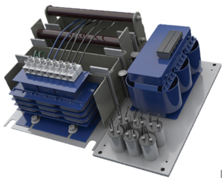
< TVS internal appearance >
◑ Main Function of TVS
The core function of the transient overvoltage suppression filter is to stabilize the system by suppressing the instantaneous voltage fluctuations.
The technical effects are summarized as follows.
√ Technical standard: Support for ASD operation of general motors under NEMA MG1 Part 30 (Part 31)
√ Core function: Suppresses the instantaneous overvoltage fluctuations caused by rapid dv/dt
√ Technical effect: Extends the life of related devices such as motors and power supply cables by reducing the vibration, noise,
and heat generation of the system
√ Effect of reducing the constant load operating current
◑ Basic Circuit of TVS
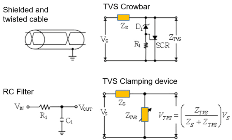
< Basic circuit of TVS >

The inverter converts AC voltage to DC and then back to AC to drive the motor. The AC voltage that is created is not the smooth sine wave that we have
traditionally recognized, but a step-like PWM waveform. This is an abnormal waveform for driving the motor and causes the following problems:
√ Motor overheating
√ Increased vibration and noise
√ Insulation breakdown
√ Shortened bearing life
√ Increased EMI (electromagnetic interference)
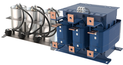
< Sine wave filter appearance >
◑ Product Feature of SWF
√ Technical Standard: NEMA MG1 Part 30 Supports ASD operation of general motors (Part 31)
√ Minimizes adverse effects due to momentary over voltages caused by rapid dv/dt transients
√ Protects motors, cables, and other related equipment by reducing noise, vibration, and heat generation
√ Reduces continuous operating current
◑ Basic Circuit of SWF
1) 3 phase, dV/dt sine wave filter
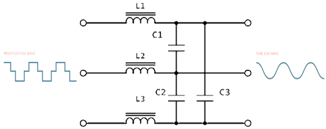
< 3 Phase SWF Basic Circuit >
2) Square wave to Sine wave Filter
Below is a circuit that uses a low-pass 3-stage RC series network to remove harmonics from a PWM or square wave signal and pass only the
fundamental wave to create a clean sine wave. Each stage gradually suppresses harmonic components, so that only the fundamental wave
remains, resulting in a high-quality sine wave.
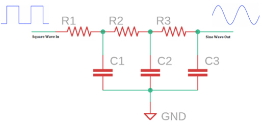
< Circuit of 1-phase square wave to sine wave conversion >

The HG-Matrix low-pass filter device can reduce the overall distortion of the load current to a maximum of 5%. It detects harmonics generated from the lower stage and actively generates and injects reverse current with the same phase and amplitude, thereby improving the stability and power quality of the system.
◑ Main Function of HG-M Filter

Among the methods of removing harmonics, the filter device that removes harmonic current using inverter control technology is called an active harmonic filter. This active harmonic filter analyzes the harmonic current generated from a nonlinear load in real time (the amount generated by harmonic order) and generates the corresponding harmonics necessary for removal with a very fast response speed and supplies them to the power circuit. The corresponding harmonic current generated from this active harmonic filter appears as a vectorial addition with the harmonic current generated from
the nonlinear load.
|
|
|
|
|
AHF Filter internal arrangement |
AHF Filter external appearance |
|
◑ Operation Concept of Active Harmonic Filter

Example. > When the 5th harmonic current ① generated from a nonlinear load is +100A,
If the 5th harmonic current ② generated in response from a harmonic filter is -97A,
What is the value of the harmonic current remaining in the power system?
Ans. > Since it is the vector sum of the harmonics generated on the load side, and the corresponding harmonics are as follows;
① +② = 100+(-97) = +3A
◑ Basic Circuit of Active Harmonic Filters
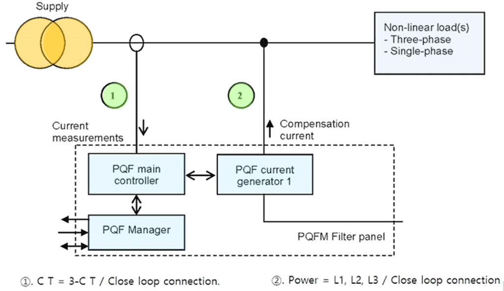
< Basic Circuit of active Harmonic Filters >

The APF system is also called an active power filter, and is composed of the latest three-stage active filter that integrates and controls three control functions: harmonics, reactive power, and unbalanced loads. The APF is designed to actively and very quickly remove harmonic components that are introduced into the power grid by nonlinear loads, thereby ensuring the safety of the system.
|
|
|
|
|
Panel type APF system |
Rack type APF system |
Module type APF System |
◑ Harmonics Removal Principle of APF
◎ Harmonic spectrum analysis
The APF device measures and analyzes the load current to reduce harmonics and calculates the harmonic current spectrum through an advanced control algorithm programmed in the DSP. The APF product series supplied by our company uses the Fast Fourier Transform (FFT) logic calculation formula for the harmonic current spectrum from the 2nd to the 50th order. This logic calculation formula determines the amplitude of the inverse harmonic current to be injected with the opposite phase angle for each harmonic order selected for harmonic reduction.

< Harmonic current spectrum analysis and PWM waveform generation >
◎ PWM waveform for compensation current generation
The compensation current generation circuit (Active Filter) sends a control signal to the high-speed IGBT through pulse width modulation (PWM), which in turn generates and injects into the system an inverse harmonic current with a completely opposite phase for each harmonic current, thereby canceling out the harmonic current to be removed.

< PWM waveform for generating reverse harmonic compensation current >
◎ Reverse harmonic generator circuit

< 3-level topology inverse harmonic generation circuit >
◎ Unbalanced load distribution (balancing) and reactive power compensation

< Load balancing and reactive power compensation circuit >
◑ Selection of APF System Spec.
APF products supplied by Seonjinhitech are structured to be installed in cabinets or wall-mounted modules, and their main specifications are as follows.
|
No. |
Parameter |
Specification |
Remark |
|
1 |
Rated Voltage Range |
AC 400V / 440V / 560V~880V |
Wide Voltage selection range, (+/-20%) |
|
2 |
Operation Frequency |
50 / 60Hz |
Selectable |
|
3 |
Parallel Operation |
Unlimited |
|
|
4 |
Overall Efficiency |
≥ 97% |
|
|
5 |
Power Grid structure |
3p-3w, 3p4w |
|
|
6 |
C.T |
50/5 ~ 5000/5 |
|
|
7 |
Rated Capacity |
30A/50A/75A/100A/150A |
|
|
8 |
Harmonic current compensation(HFC) |
2차 ~ 50th Hamonics, THDi < 5% |
Dynamic real-time compensation control |
|
9 |
Filtering angle |
Adjustable 2 ~ 50 |
|
|
10 |
Reactive power compensation |
-1 ~ +1 of full range |
Capacitive, inductive bidirectional load real-time compensation control |
|
11 |
Automatic Power Factor compensation(APFC) |
~ 0.99 |
Dynamic real-time compensation control |
|
12 |
Unbalanced load control |
3-phase unbalanced load balancing |
Unaffected by system imbalances |
|
13 |
Control response time |
<10ms |
Swap time |
|
14 |
Quick / Full Response time |
≤40μs / ≤10μs |
Dynamic real-time control cycle |
|
15 |
Switching Frequency |
20kHz |
IGBT cell, System Voltage Improvement |
|
16 |
Interface / Communication |
RS-485, MODBUS, 4G, WiFi, Ethernet |
Cloud customization support |
|
17 |
HMi Function |
GUi based on Self-backlit LCD 4.3’ touch screen |
Directly set Op’ parameters through its own LCD Control monitoring of operating status such as power factor/ harmonics/load Alarm, event, fault report |
|
18 |
PC software |
Optional |
Parameter set, monitoring |
|
19 |
Protection Control |
Grid OV protection Load OC, OL Protection
System OT Protection |
System overvoltage/under voltage, phase failure, bus overvoltage / under voltage, 3-phase instantaneous over current/overload current, power side fault, overheat/fan failure, fuse failure |
|
20 |
Measurements |
Provides real-time monitoring of operation data for system analysis |
Network RMS - V, RMS - I, THD - V, THD - I Total RMS load current System frequency Load factor, Power factor Compensated RMS current Comparison of PF (after to before) Graphic chart for V, I, P, compensated - I Harmonic spectrum : 2~50 order of load current |
|
21 |
Fault Alarm |
500 Alarms recordable |
Alarm, Event, Failure information |
◑ APF Products Model Series
|
Solution type |
Specification |
Geometry Size |
|
|
30A |
Rack-Mounted |
APF(R) - 30A Single rack mount module W453 x D450 x H86 (mm) 14kg |
|
|
Wall-Mounted |
APF(W) - 30A Wall mount module W423 x D88 x H550 (mm) 15kg |
|
|
|
50A |
Rack-Mounted |
APF(R) - 50A Single rack mount module W453 x D450 x H86 (mm) 14kg |
|
|
Wall-Mounted |
APF(W) - 50A Wall mount module W423 x D88 x H550 (mm) 15kg |
|
|
|
75A |
Rack-Mounted |
APF(R) - 75A Single rack mount module W551 x D540 x H190 (mm) 35kg |
|
|
Wall-Mounted |
APF(W) - 75A Wall mount module W503 x D190 x H597 (mm) 36kg |
||
|
100A |
Rack-Mounted |
APF(R) - 100A Single rack mount module W551 x D540 x H190 (mm) 35kg |
|
|
Wall-Mounted |
APF(W) - 100A Wall mount module W503 x D190 x H597 (mm) 36kg |
|
|
|
150A |
Rack-Mounted |
APF(R) - 150A Single rack mount module W558 x D540 x H220 (mm) 44kg |
|
|
Wall-Mounted |
APF(W) - 150A Wall mount module W503 x D220 x H608 (mm) 45kg
|
|
|
l Cabinet/Panel type APF
|
Solution type
|
Specification
|
Geometry Size
|
|
|
up to
750A
|
400V APF
|
APF(C) – 400V
Control
for : PF ~ 0.99, and THD < 5%
Compensation for : 2~50 order harmonics Capacities and inductive reactive power and 3-phase unbalance load
|
|
|
480V APF
|
APF(C) – 480V
Control
for : PF ~ 0.99, and THD < 5%
Compensation for : 2~50 order harmonics capacities and inductive reactive power and 3-phase unbalance load
|
|
|

The stationary reactive power compensator (SVC) is a stationary reactive power compensator that actively controls reactive power with a function similar to that of a synchronous generator. It is used to maintain stable voltage by actively adjusting the power factor of the power system and to improve the overall power quality, such as increasing the capacity of transmission lines. It is also useful for limiting voltage fluctuations on the bus due to rapidly changing loads, such as suppressing over voltages and improving system voltage stability.
◑ SVC External Appearance
|
|
|
|
|
Exterior appearance of Static Var Compensator |
Internal Arrangement of Static Var Compensator |
|
◑ Main Function of SVC
If the reactive power in the system is not compensated, the phase change of voltage (V) and current (I) according to the capacitive and inductive load characteristics is shown below.

< Phase change of voltage (V) and current (I) according to load characteristics >
For the above reasons, the SVC system effectively compensates for the capacitive or inductive reactive power required for the system according to the load characteristics by controlling the line constant of the system by connecting it in parallel to the bus of the power system, thereby improving the power factor, minimizing the voltage fluctuation and harmonic influence caused by nonlinear load, and improving power quality such as three-phase load balance, thereby reducing unnecessary power loss and contributing to improving productivity and product quality. The main functions are summarized
as follows:
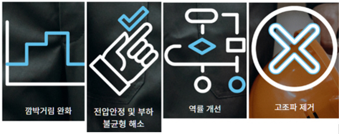
√ Resolving dynamic load imbalance with voltage stabilization and regulation function
√ Reducing voltage drop even in sudden load fluctuations to alleviate flickering
√ Improving power factor by compensating for inductive or capacitive reactive power
√ Removing harmful harmonics

◑ Economic Advantage of SVC
√ Improve factory manufacturing productivity
√ Extend the life of electronic equipment by stabilizing voltage
√ Save money by reducing heat loss through improved energy efficiency
√ Reduce power costs for power utilities and other customers
√ Minimize disturbances to adjacent customers by mitigating flickering
√ Minimize malfunctions of protective devices, etc. by reducing harmonics
√ Improve real power transmission efficiency
√ Reduce facility maintenance costs
◑ Basic Circuit of SVC
SVC is a device that controls the combination of reactors and capacitors that affect the line constant with a thyristor. It is connected in parallel with the bus and directly controls the line constant of the system, thereby also having a harmonic filter function.
√ TCR (Thyristor Controlled Reactor) method: A method that phase-controls the current flowing through the shunt reactor with a thyristor
√ TSC (Thyristor Switched Capacitor) method: A method that switches the capacitor bank with a thyristor

< Basic Circuit of SVC with TCR & TSC >

< Basic Circuit of SVC with TCR & Controller >
◑ Application area of SVC
1) Power Transmission system
Real-time control of reactive power during long-distance transmission maintains voltage stability and improves transmission efficiency.
2) Large Scale of industrial facilities
Compensates for voltage instability caused by rapid changes in loads such as arc furnaces, blast furnaces, and large motors in steel mills,
smelters, and cement plants.
3) Electric railway system
Stabilizes instantaneous voltage fluctuations that occur during the operation of electric trains to maintain power quality in the railway
power system.
4) Renewable energy power generation complex
Compensates for voltage fluctuations and reactive power in power sources with irregular outputs such as wind or solar power generation
to improve grid connection stability.
Compensates for reactive power generated at the connection point with the high-voltage direct current (HVDC) system to help stabilize
the voltage of the AC system.

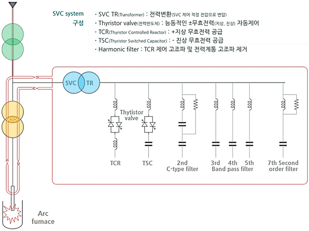
◎ SVC Application Cases (A large capacity of Arc furnace) __________________
The following is an application example in an industrial field, explaining the application effect of the SVC system in an Arc Furnace in the steel
making process.
1) SVC System Configuration
Basically, TCR and TSC are configured together to enable real-time alternating control of inductive (L) and capacitive (C) loads depending on
driving conditions.
2) SVC system application specifications
① SVC compensation capacity: 0~400Mvar
② Bus controllable voltage: 6~500kV
③ SVC rated voltage: 6~66kV
④ Total dynamic response time (reactive power output): <15ms
⑤ SVC availability: >99%
⑥ SVC maximum loss: <0.8%
3) SVC system application effects
① Optimal operation for power factor improvement of large-capacity electric furnaces (arc furnaces, induction furnaces, DC furnaces)
with extreme load fluctuations
② Suppress flickering and prevent malfunction of various protection devices by stabilizing voltage
③ Increased melting capacity (shortened melting time and improved productivity)
④ Reduced electrode replacement cost (extended replacement cycle)
⑤ Reduced wear of electric furnace lining by stable arc supply
⑥ Reduced power loss

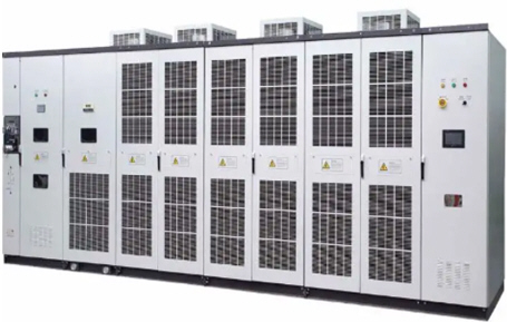
SVG(Static Var Generator) is also called real-time reactive power generator or active power factor compensator (APFC). It is a representative technology in the field of reactive power compensation as the ultimate solution to improve low power factor and various power quality problems caused by increased reactive power. SVG is connected in parallel to the power grid bus and operates as a variable reactive current supply source.


◑ Main Function of SVG
SVG can quickly absorb or release all the required reactive power by adjusting the voltage amplitude and phase on the AC output side of the inverter, or by directly controlling the amplitude and phase by measuring the AC current, so it can achieve its purpose very quickly. By controlling the DC component by adjusting the reactive power in the system, it is possible to track and compensate for the inrush current of the impulse load as well as track and compensate for the harmonic urrent. Recently, by using power electronics inverter technology, it has become possible to control the power factor close to 1 by generating a reverse current of the opposite phase with the same size as the compensation target and canceling each other out. In addition, SVG is high-performance electronic module that can respond immediately and effectively to power quality problems in the power supply system and also has a kind of active filter (APF, Active Power Filter) function. The main functions of SVG are summarized as follows.
√ Real-time reactive power compensation by using high-speed IGBT devices
√ Active harmonic filter function prevents various harmful effects due to harmonics such as overheating and malfunction of equipment
√ Improves equipment stability, reliability, and lifespan by tracking and controlling various abnormal voltages, inrush currents, etc.
√ Increases power system capacity by reducing energy loss
◑ Basic Circuit of SVG
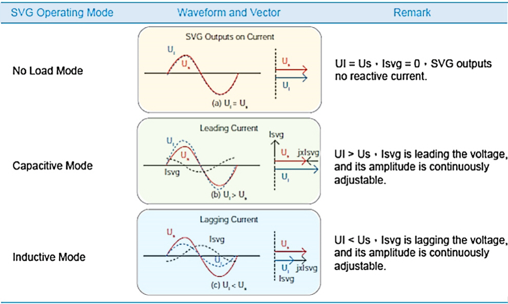
SVG is a power electronic circuit device that is connected in parallel with a load that requires power factor improvement or harmonic reduction, and when the load generates inductive or capacitive current, it generates a voltage corresponding to the load current. At this time, it detects the phase difference between the current and voltage on the load side, generates Lead or Lag current in real time, and injects it into the bus to make the phase angle of the load current almost identical to the phase angle of the voltage, and continuously maintains the basic power factor.
.
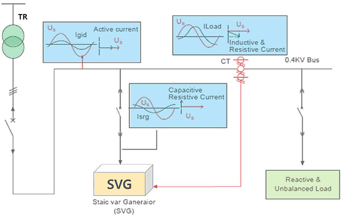
< Configuration of basic circuit of SVG >
◑ SVG System Operation Principle and Characteristics
In a system with a load, if the power factor drops, the energy loss of the facility increases, which also adversely affects the stability of the facility.
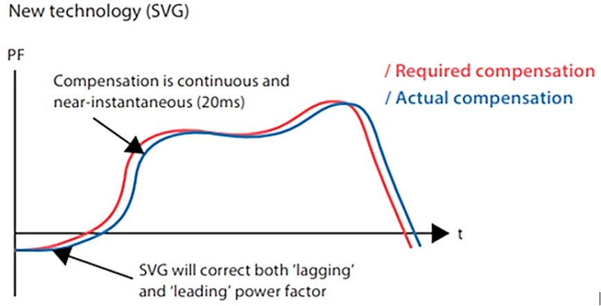
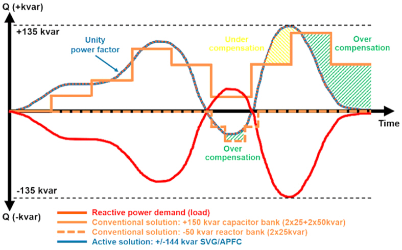
his phenomenon is caused by inductive or capacitive loads that require reactive power for the system to operate properly. Another cause of thepower factor drop is harmonic currents generated by nonlinear loads and load fluctuations in the power system. In response, SVG supplies inductive or capacitive reactive power in real time, and the fast response characteristics of SVG solve the problem of rapid response that is difficult to implement with existing capacitor banks or reactor banks, thereby enabling very stable and accurate power factor compensation.
◎ Power factor compensation characteristics by conventional capacitor compensation method
(stepwise, intermittent control)

< Power factor compensation characteristics by conventional capacitor compensation method (stepwise, intermittent control) >
◎ Power factor compensation characteristics by new technology SVG control method
(Stepless, continuously controled)
|
items |
Conventional L-C Bank |
Advanced SVG System |
|
Response time |
MC based: 30~40s required THY’ base: Relaxed to 20~30ms |
Real-time response possible with total response time less than 100 µs |
|
Output |
No real-time matching to load due to Step. Varies with grid voltage due to use of C, L |
Real-time, continuous, seamless operation Not affected by grid voltage |
|
PF compensation |
Inductive load requires C bank, capacitive load requires L bank. There is a problem in a mixed load, and a constant PF is not guaranteed due to the step. |
Real-time simultaneous correction of lag/lead area from -1 to +1 |
|
imbalance Load |
Load imbalance cannot be corrected |
Optional compensation of load imbalance amount |
|
Design Range |
L, C capacity determination requires prior reactive power study, Generally requires L, C with larger capacity than calculated capacity. Need to design considering system harmonics, specific load and network, Need to be customized to suit conditions |
No need for extensive research as it is real-time automatic adjustment, The relaxation capacity is optimized during operation, It is not affected by harmonic distortion of the system, It automatically adapts to load fluctuations and network conditions. |
|
Resonance effect |
Series and parallel resonance can amplify system current |
No risk of harmonic resonance with the network |
|
Transient phenomenon |
Caused by switching of C bank or branch reactor |
Does not occur (no passive component transition) |
|
Over load |
Caused by slow response or large load fluctuations |
Does not occur because the current is limited to a maximum value (RMS) |
|
Installation area |
Large space requirement in case of harmonic order, and difficulty in expansion when load is frequently upgraded |
Because the module size is small, the installation area is small and installation is easy, Existing switch can be used |
|
Expansion Ability |
Limited and subject to load and network conditions |
Very simple, just add modules |
|
Maintenance/ Life cycle |
Components such as fuses, CB, CS, L, C, etc. are required for extensive maintenance and their lifespan is shortened due to switching, transient current, resonance, etc. |
Easy maintenance due to no electromechanical switching and no risk of failure, and a service life of at least 15 years due to no transients or resonances. |
√ Installations with rapidly changing reactive power demands, such as electric arc furnaces and ball mills
√ Highly dynamic loads with rapidly fluctuating power factors or large load currents, such as cranes, sawmill machinery, welding machines, etc.
√ Loads with low power factor: motors, cables, light-duty transformers, lighting, etc.
√ Inverters for solar inverters and wind turbines
√ Electrified railway systems: trains and trams

√ PF maintenance: 0.99
√ Capacitive, inductive reactive power compensation: -1 to +1
√ Harmonic filtering: 2nd to 12th harmonic
√ 3-phase unbalanced load compensation
√ Generates inductive or capacitive reactive power, injects it complementarily to improve power factor
√ Operates as a voltage source with PWM control, responds so quickly to sudden load changes, stabilizing voltage and resolving load imbalance
√ Responds within a few ms with high-speed IGBT control, quickly eliminating voltage distortion caused by harmonics
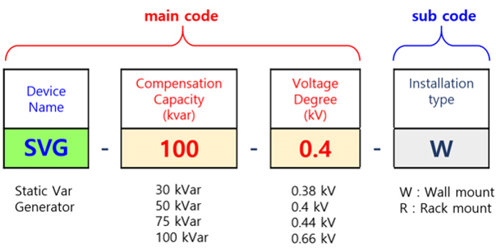
|
Parameter |
Specification |
Remark |
|
Rated Voltage Range |
AC 380V*, 110V ~ 690V |
+/-20% |
|
Operation Frequency |
50 / 60Hz |
Selectable |
|
Parallel Operation |
Unlimited |
|
|
Overall Efficiency |
≥ 97% |
|
|
Power Grid structure |
3p-3w, 3p4w |
|
|
C.T |
50/5 ~ 5000/5 |
|
|
Rated Capacity |
30kVar / 50kVar / 75kVar / 100kVar / 500kVar |
120kVar / 500kVar |
|
Harmonics Filtering |
2'nd ~ 12'th harmonics, THDi < 5% |
Dynamic real-time compensation control |
|
Filtering Angle |
Adjustable, 2 ~ 50 |
|
|
Reactive power compensation |
Adjustable, -1 ~ +1 |
Capacitive, inductive bidirectional load real-time comp. control |
|
Auto. PFcompensation(APFC) |
~ 0.99 |
Dynamic real-time compensation control |
|
Imbalance Load Control |
3-phase unbalanced load balancing |
Unaffected by system imbalances |
|
Control Response time |
<10ms |
Swap time |
|
Switching Frequency |
20kHz |
IGBT cell, Improve system voltage |
|
Interface, Communication |
RS-485, MODBUS, 4G, WiFi, Ethernet |
Cloud customization support |
|
HMi Function |
Self-backlit LCD based GUI 4.3’ touch screen |
Direct Op’ parameter setting through own LCD Power factor/harmonics/load |
|
PC software |
Optional |
Parameter set, monitoring |
|
Protection Control |
Grid OV protection Load OC, OL protection System OT protection |
System overvoltage/undervoltage, phase failure, bus overvoltage/undervoltage, 3-phase instantaneous overcurrent/overload current, power side fault, overheating/fan failure, fuse failure |
|
Measurements |
Operation data for system analysis Provides real-time monitoring |
Network RMS - V, RMS - I THD - V, THD – I, Total RMS load current System frequency, Load Power Factor Compensated RMS current Comparison of PF (after to before) Graphic chart for V, I, P, compensated - I Harmonic spectrum : 2~50 order of load current |
|
Fault Alarm |
500 Alarms recordable |
Alarms, events, and fault information |
3) Selection of LV - SVG installation spec.
|
|
|
|
|
Rack mount type |
Wall mount type |
Panel/Cabinet type |
|
Installation |
Rack Mounted |
Wall Mounted |
||||
|
Dimension |
30 / 50 kVar |
75 kVar |
100 kVar |
30 / 50 kVa |
75 kVar |
100 kVar |
|
W |
452.5 / 472 |
550.6 |
558 |
423 / 503 |
503 |
503 |
|
H |
450 / 540 |
540 |
540 |
88 / 122 |
190 |
220 |
|
D |
86 / 122 |
190 |
220 |
550 / 558 |
597 |
608 |
5) Selection of LV - SVG product model
|
800V |
110 kVar |
|
|
|
|
|
|
3p3w |
|
690V |
120 kVar |
|
|
|
|
|
|
3p3w / 3p4w |
|
440/480V |
30 kVar |
83 kVar |
|
|
|
|
|
3p4w |
|
440/480V |
12 kVar |
20 kVar |
30 kVar |
60 kVar |
80 kVar |
100 kVar |
|
3p3w |
|
400V |
5 kVar |
10 kVar |
20 kVar |
30 kVar |
50 kVar |
75 kVar |
100 kVar |
3p3w / 3p4w |
|
220V |
3 kVar |
5 kVar |
10 kVar |
15 kVar |
20 kVar |
30 kVar |
55 kVar |
3p3w / 3p4w |
6) Selection of LV - AHF / SVG product customizing model
|
Mini AHF/SVG |
Fanless AHF / SVG |
800V, Power Pro AHF / SVG |
Water Cooling AHF / SVG |
Outdoor AHF / SVG |
Fully sealed AHF / SVG |
|
10A / 5kVar |
10A / 5kVar |
80A / 110kVar |
100/150A, 75/100kVar |
100/150A, 75/100kVar |
100/150A, 75/100kVar |
|
|
|
|
|
|
|
|
Better sampling accuracy it is the new market oppertu -nity to eliminate 0-1kVar capacitive power |
Lower noise it is used in office, hotel, store andrestrant etc, |
Higher voltage support it will be use in PV plant to solve PF problems |
Better heat dissipation it is a good solution for data center |
High potential level it is a new market oppertunity in outdoor power quality project |
More harsh condition it is used in very harsh condition (conductive dust) |
◑ HV-SVG Product Series
All HV-SVG series products supplied by us Seonjinhitech have the same systematic structure and performance, so any product guarantees customer friendly operating flexibility and reliability.
|
|
|
|
HV-SVG indoor type |
HV-SVC outdoor type |
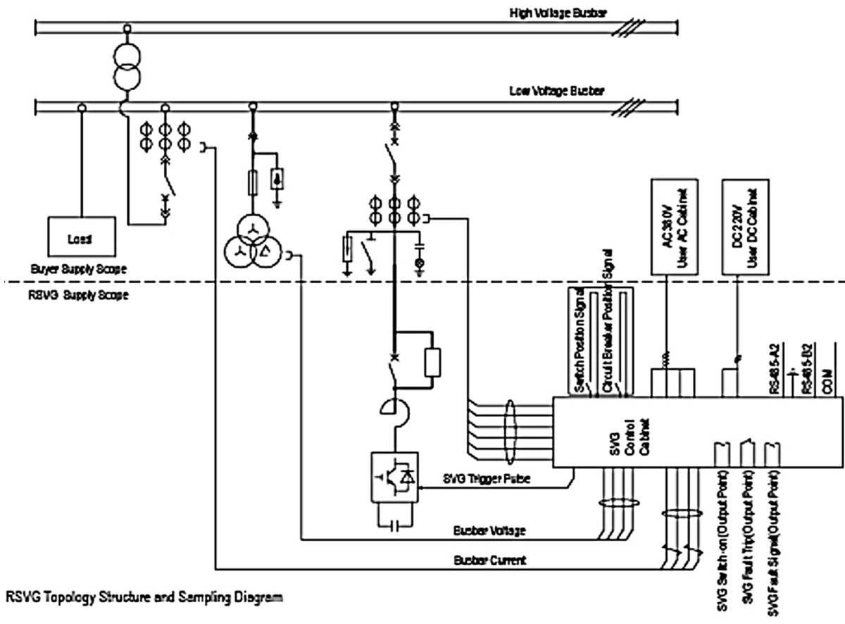
◎ Basic Circuit of HV-SVG Series
◎ HV - SVG Quality Assurance
- 100% quality inspection of all applied parts
- Operation of advanced automatic welding and inspection system
- Applying dustproof, waterproof and anti-static paint
- High temperature and low temperature aging and testing
- Military grade electromagnetic wave and high voltage resistance testing
- Operation of full load testing equipment up to 200MVA
◎ HV - SVG System Advantages
- Fully automatic diagnosis during startup
- Improved communication reliability and response time through DSP and FPGA technology
- Application of military-grade communication error code detection technology
- Application of dual power supply to resolve UPS instability
- Application of flexible startup technology to prevent network collision
- Dualization and modular design of main devices
- Real-time monitoring of instantaneous reactive current and power based on theory
- Application of PWM current tracking control technology
- Application of DC side voltage smoothing control technology
- Control of DC current with a fast response speed of up to 5 ms
- Application of multi-compensation functions (reactive power compensation, harmonic current compensation, reverse current compensation, and comprehensive monitoring compensation)
- Adoption of open communication I/F protocols such as Modubus, IEC61850, 103, and 104
- One-button operation and automatic operation throughout the entire process through application of integrated system operation design
- Programmable I/O connection interface provided free of charge
- Accurate fault location identification through complete modularization design (5-minute fault response)
- Integrated design based on customization enables immediate operation upon on-site installation (Test drive omitted)
◎ HV - SVG System application areas

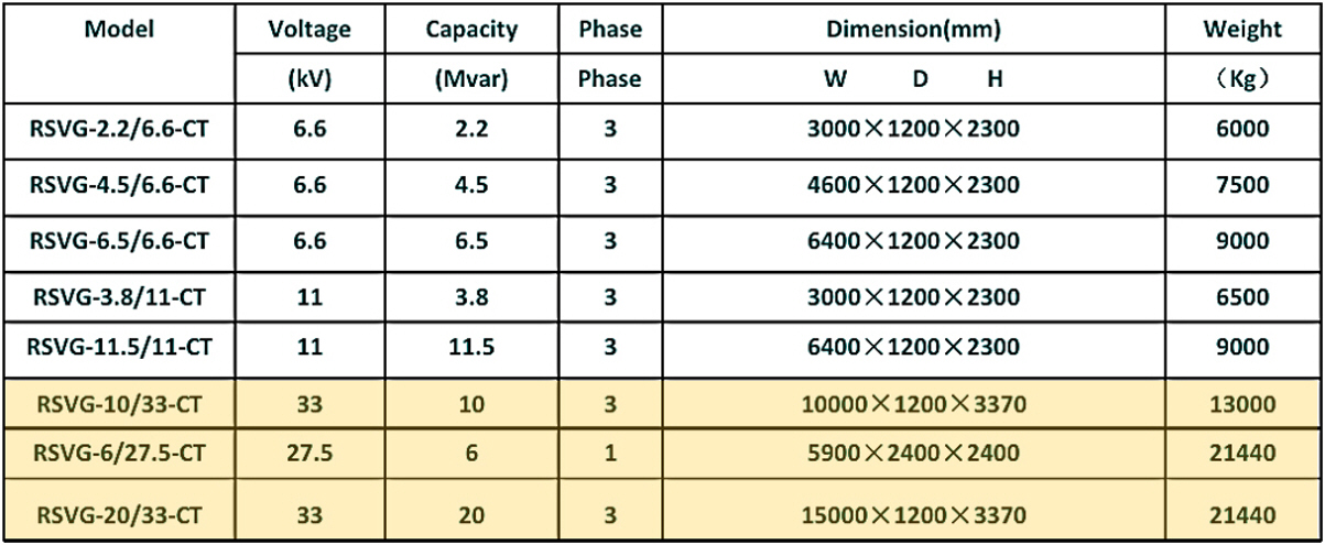

☞. Note:27.5kV 와 33kV 시리즈는 리엑터를 포함하지 않는다.

Most industrial electrical equipment has inductive load characteristics. Therefore, in order to operate them efficiently, it is necessary to supply and offset the corresponding capacitive reactive power with the opposite characteristics. This reactive power can be supplied by installing a capacitor bank in parallel with the load. If the capacitor bank is used with a capacity corresponding to the inductive load, the power factor can be maintained at almost 1. This type of power factor improvement is ultimately a process of reducing the phase difference between the voltage and current on the load side.
Basically, the capacitor bank performs the function of restoring the load current on the lagging side to normal by creating and injecting a leading current.
|
|
|
|
|
LV-CB indoor type |
HV-CB indoor type |
HV-CB outdoor type |
◑ Basic Circuit of Capacitor Bank
Capacitor banks are composed of multiple capacitors connected in series or parallel, and are mainly used to improve the power factor of power systems, stabilize voltage, and reduce harmonics. The main devices that make up capacitor banks are as follows, and protective devices such as circuit breakers, relays, and current transformers are also configured as needed.
√ Capacitor
√ Serial Reactor
√ Discharge Coil
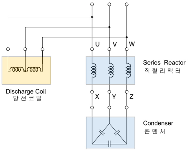
< Basic configuration of capacitor bank for power factor improvement >
◎ Capacitor
Capacity determination of a capacitor for power factor correction is mainly carried out in the following order.
① System power factor analysis
System current power factor analysis
Load calculation (Check the power factor of the entire load)
Check the power factor of each system where the capacitor will be installed
② Target power factor setting
Set the desired target power factor (power factor required by each country is slightly different)
In Korea, KEPCO requires 0.9, but in reality, the power factor can vary depending on the load, so set the target value to at least 0.93
③ Calculate the required compensation capacity
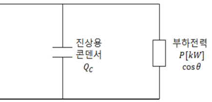
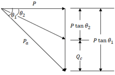
The capacity of the capacitor for power factor compensation can be calculated using the following calculation formula.
Where,
P (kW): Active power used in the system (kW)
θ1: Current power factor value (cosθ1: Current power factor)
θ2: Target power factor value (cosθ2: Target power factor)
Required capacitor capacity: Pr (kVar)
Pr = P (kW) x tan (θ1-θ2)

④ Select capacitor capacity
Based on the calculated capacitor capacity, select a capacitor with an appropriate capacity that can be purchased on the market
If the capacity is very large or a power factor compensation device is used, calculate the number of steps and the capacitor capacity
of each unit per step. Usually, three banks are installed and the capacity of each bank is different, so that the control resolution can
be increased depending on the combination.
Ex. > If a total capacity of 3000 kVar is required,
Ans. > By configuring three banks with capacities of 500, 1000, and 1500 kVar,
a total of six steps of 500, 1000, 1500, 2000, 2500, and 3000 kVar can be created with the combination.
◎ Series Reactor
The series reactor in the capacitor bank has two main functions: inrush current limiting function and harmonic current limiting function.
① Inrush current limiting reactor
It is applied to reduce the starting current by suppressing the terminal voltage in a load with a large starting current such as an
induction motor and to reduce the circuit breaker capacity. If it is used only for the inrush current limiting function at the start,
the reactance is 0.2%, and this value varies depending on the design conditions. In this case, the inrush current can be up to
1 + √(1.0 / 0.002) = 23.4 times.
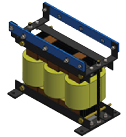
< inrush starting current limiting reactor >
② Harmonic current limiting reactor
It is connected in series with a capacitor for power factor improvement to reduce harmonics and protect the capacitor.
The harmonic reduction reactor usually applies a reactance of about 6%, and in this case, the inrush current can be up to 5.1 times.
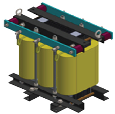
< Harmonic current limiting reactor >
☞. Types and insulation methods of REACTOR CORE
The core types of reactors are air core and iron core, and the insulation methods are dry type and oil type.
Air core: It can only be manufactured dry, and it is difficult to build a cubicle with only a coil, so it is mainly installed outdoors.
Iron core: It can be manufactured dry or inflow type, and it can be built into a cubicle.
In the case of inflow type, it cannot be installed indoors, and even if it is installed outdoors, measures against oil leakage are required.
◎ Discharge Coil
The purpose of the discharge coil is to remove the residual voltage of the capacitor circuit and prevent overvoltage applied to the capacitor when
reinserted into the line. If the residual voltage can be lowered below the specified value by the discharge resistance built into the power capacitor
alone, a separate discharge coil does not need to be installed. However, if it is absolutely necessary due to the characteristics of the equipment,
such as high voltage and large capacity, a separate discharge coil must be installed.
☞. Discharge characteristics of power capacitors
KS C 4802 High voltage and extra high voltage power capacitors à Discharge within 5 minutes, 50 V or less
KS C IEC 60871-1 Shunt capacitors for AC systems with rated voltage exceeding 1000 V à Discharge within 10 minutes, 75 V or less
KS C 4804 Discharge coils for high voltage and extra high voltage phase-leading capacitors à 50 V or less after 5 seconds of starting
discharge
◑ Capacitor Bank Installation and Maintenance
Power factor correction capacitors can greatly help improve the efficiency of the power system and reduce electricity bills, so power factor management
can be a very important issue. Also, the capacity of capacitors can decrease over time, so regular inspection and maintenance must be performed after
installation in the system.

Reactor bank is configured in various ways depending on the purpose. For power, it is mainly used to suppress abnormal voltage by limiting surge
current or inrush current. When installed in combination with a capacitor, it has the function of eliminating harmonic waves generated by the capacitor
and also has the effect of improving the voltage waveform by suppressing inrush current and overvoltage.
|
|
|
|
|
|
iron core reactor |
air core reactor |
dry type reactor |
oil type reactor |
◑ Reactor Functions and Features by Application
The reactors applied to power circuits are classified according to their purpose and function as follows:
√ Serial reactor: Eliminates harmonics and improves voltage waveform
√ Shunt reactor: Prevents transmission line ferenty phenomenon
√ Current limiting reactor: Limits fault current, short-circuit current, and inrush current
√ Neutral point grounding reactor: Limits ground fault current and suppresses abnormal voltage in case of ground fault
√ Small arc reactor: Extinguishes arc in case of ground fault
◎ Series Reactor for Harmonic Suppresion
① Harmonic elimination and voltage waveform improvement
The biggest problem when connecting a capacitor to a transmission line for use as a voltage source is the distortion of the voltage waveform.
This is because the harmonic voltage is induced due to the magnetic saturation phenomenon of the transformers on the line, and the harmonic
voltage is amplified when the capacitor is connected. Among them, the third harmonic voltage is eliminated by the delta connection on the
low-voltage side of the transformer, and the fifth harmonic voltage remains without being eliminated.
② Surge current limitation
A reactor is connected in series to an AC circuit to limit the inrush current or short-circuit current or to limit the current sharing of a paralle
l circuit. A reactor that limits the current during a short circuit is also called a current-limiting reactor, and it is common to require a relatively
small reactor whose voltage drop is about a few percent of the phase voltage when the rated current is applied.
③ 5th harmonic current limitation
The impedance for the 5th harmonic can be increased by connecting it in series with a capacitor for power factor improvement, thereby
limiting the amount of harmonic inflow. For this purpose, the capacity of the reactor applied is about 6% of the capacitor capacity, and a
gapped core reactor is mainly used. In cases where the 3rd harmonic is included in large quantities, a capacity of about 13 to 15% is used,
and the margin is appropriately about +20 to 30% of the guaranteed value.
④ Characteristics of air-core reactors
They are mainly used between the two ends of transmission lines because their reactance values are constant and stable regardless
of the size of the current.
⑤ Precautions for using iron-core reactors
Since the impedance of series reactors is specified according to the maximum fault current of the system, when using iron-core reactors,
which have a phenomenon in which reactance is distorted at the magnetic saturation point, care must be taken to ensure that they are
operated only in sections where the iron core is not saturated.
◎ Shunt Reactor
① Transmission line leading current compensation
Shunt reactors are connected in parallel to the transmission line busbars to compensate for the line leading current (charging current of
cables under light load). Recently, as the scale of the power system has expanded and the number of long-distance high-power
transmissions has increased due to remote power supply and load concentration, the capacitance of the cable system has increased,
which has led to an increase in the capacity of the power system's power supply equipment. Typically, short-term capacities of about 30
or 60 [MVA] are combined and used.
② Shunt reactor installation locations
Shunt reactors are basically installed at substations at both ends of the transmission line, and can also be used as a power supply equipment
function in combination with a condenser.
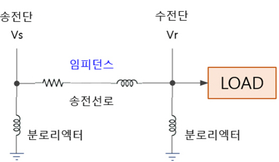
< Application of Transmission Line Shunt Reactor >
③ Types of shunt reactor applications
Shunt reactors are mainly applied to high-voltage systems, so the structure is usually an iron core type with an inlet gap or an air core
type with magnetic shielding iron pieces at the top and bottom.

< Air-Core Reactor Structure >
④ Reactance margin
Since the reactor is problematic due to eddy current loss of the core, vibration noise, etc., each manufacturer designs a structure with its own characteristics, and the reactance margin of the shunt reactor is generally applied as ±5% of the guaranteed value.
◎ Current Limitting Reactor
① Short-circuit current limiting
The current limiting reactor is used to limit the inrush current or short-circuit current flowing on the primary side when the transformer is turned on to a specified value or less. This reduces the breaking capacity of the circuit breaker and also has the function of preventing damage to the series device.

② %Z (Impedance)
As shown in the previous short-circuit current equation, the short-circuit current decreases as the reactance value increases. Here, %Z (impedance) is calculated from the following equation.

◎ Neutral Grounding Reactor (NGR)
① Grounding reactor installation location
It is connected between the neutral point of the transformer and the ground and is used to limit the ground fault current and suppress
the abnormal voltage in the event of a ground fault in a three-phase power system.
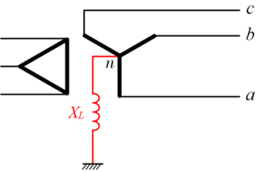
< Neutral Grounding Reactor (NGR) Installation Location >
② Limitation of Grounding Current
The neutral grounding current is proportional to the transformer capacity. If necessary, a supplementary resistor can be directly connected
and used.
③ Usage Time Rating
The current rating for short-term use is usually based on 10 seconds unless otherwise specified.
④ Impedance Margin
The impedance margin of the neutral grounding reactor is set to ±20~30%.
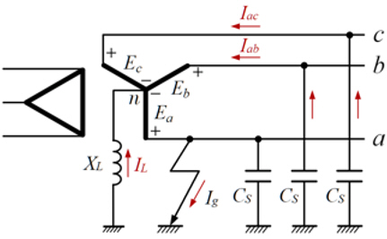
< Installation location of arc suppression reactor >

*********************************************************************************************************************************************************************************
(주)선진하이테크 / Seonjinhitech Co., Ltd.
경기도 화성시 향남읍 발안공단로 4길13 / 대표: 백용호
Tel: +82-31-8059-1387 / Fax: +82-31-8059-1397
E-Mail: sjhtech@seonjinhitech.co.kr
Website: http://seonjinhitech.co.kr


