발전기세트
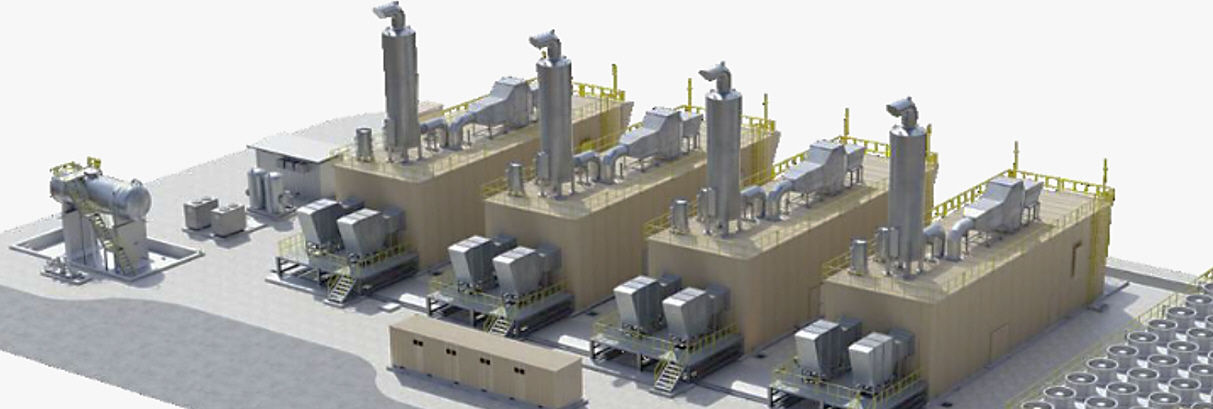
GENERATOR SET
General Description
◐ Diesel Generator Set ?
Diesel generator set is a power equipment that produces electricity by combining a diesel engine and a generator as an integrated unit. It is mainly used in emergency power supply during a power outage, or in areas where power supply from the general power grid is difficult, such as industrial facilities and construction sites.
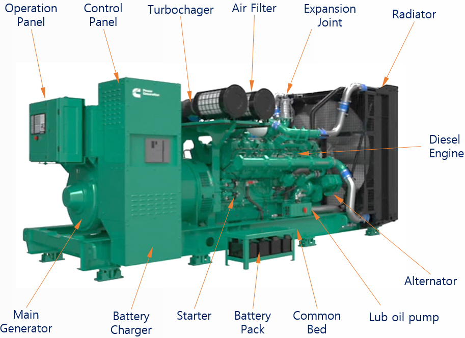
◎ Main Components
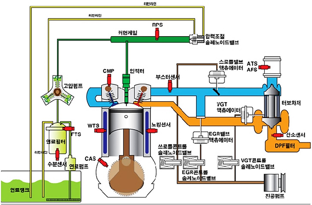
1) Diesel engine : An internal combustion engine that burns diesel fuel to generate power. Efficient and durable.
2) Generator : Converts the mechanical energy of the engine into electrical energy.
3) Control panel : Starts, stops, monitors (voltage, current, frequency, etc.), includes an automatic transfer switch (ATS) function
4) Fuel system : Includes a fuel tank, supply line, etc. Supplies diesel fuel to the engine.
5) Cooling system : Prevents engine overheating using coolant or a radiator.
6) Exhaust system : Discharges gases generated after combustion to the outside.
7) Lubrication system : Reduces friction inside the engine and extends its life.
◎ Main purpose
1) Emergency power supply : Hospitals, data centers, airports, etc. where uninterrupted power is essential
2) Main power : Power shortages areas or frequent power outages, remote islands, mountain area, etc where power plants are not supported.
3) Temporary power supply : Concerts, outdoor events, industrial construction sites
◎ Advantages
1) Fuel economy : Diesel fuel has higher energy density and is cheaper than gasoline
2) Excellent durability : Can be operated continuously for long periods of time
3) Low operating costs : Particularly advantageous for long-term operation at hourly rates
◎ Disadvantages
1) Vibration and noise : Need for dust and soundproofing measures
2) Exhaust gas: Subject to environmental regulations (SOx, NOx oxide measures required)
3) Initial cost: Relatively high compared to general power supply
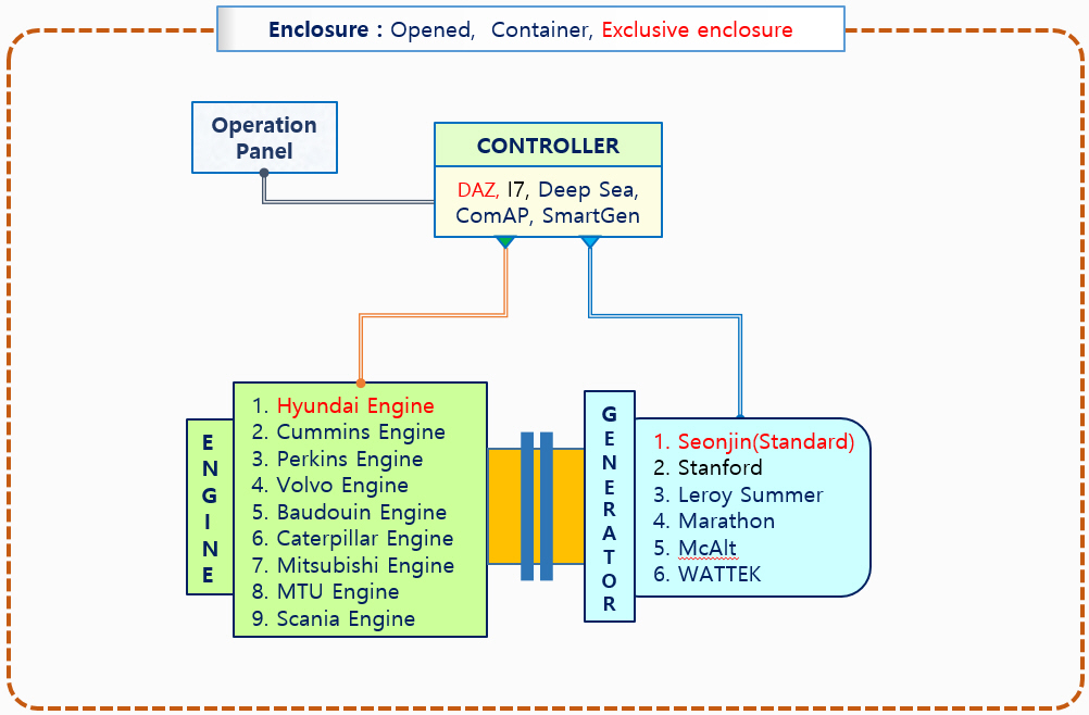
◐ Generator Configuration
|
|
 |
 |
 |
 |
 |
 |
 |
 |
 |
 |
|
HD-Hyundai |
Cummins |
Bauduin |
MTU |
Scania |
Perkins |
Mitsubish |
Caterpilla |
Volvo |
MAN |
WeiChai |
|
Parameter |
Majour Features |
|
Compact Design |
An integrated internal design allows many functions in a relatively small space and design & operation is simple and smart. |
|
Operation Panel |
Embedded(standard), or optional separated type |
|
Terminal Board |
T.B can be sitted in the left or right side of generator so that it can be freely selected depending on where load line comes out. The rear side is designed for convenient modification and maintenance in an integrated fashion. |
|
Fuel Tank |
As a fuel tank is placed in the bed frame, it is easy to use and minimized in the space. Fuel gage & feed / return line have been included. |
|
Bed Frame |
The bed frame is made of highly durable steel, and has a structure that can be equipped with supports if necessary. |
|
Main Circuit Breaker |
The main circuit breaker is equipped on the generator, making it convenient to install & manipulate load lines. |
|
Wide range of selectable power |
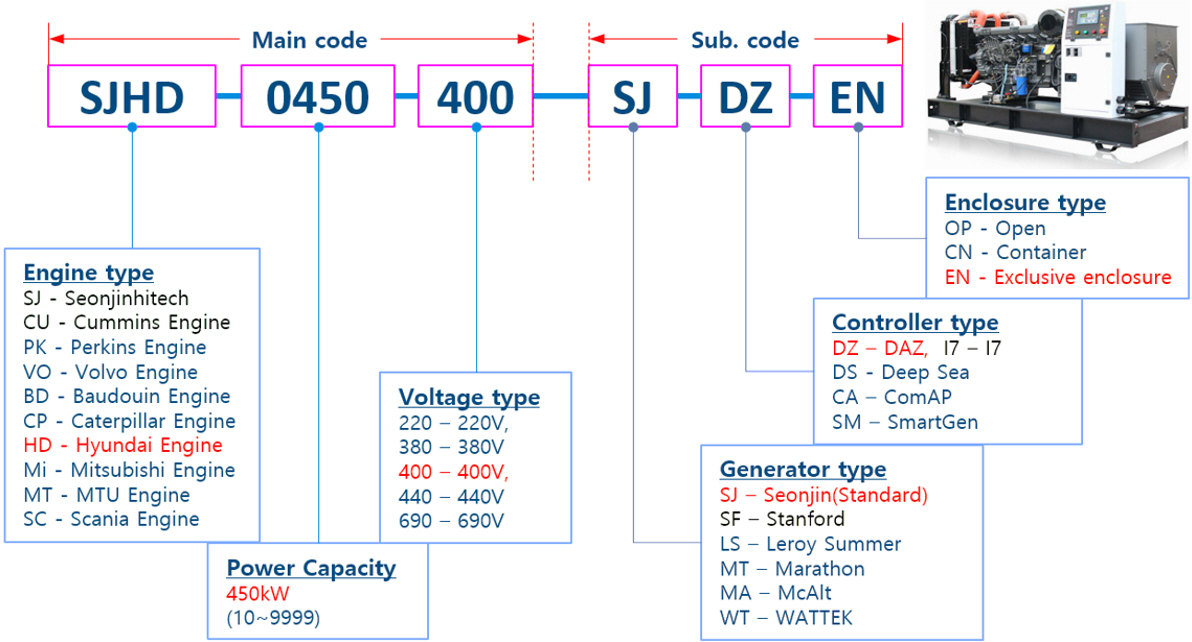
A wide range of types from small size(10kW) to large size(5000kW), low to medium/high voltage and from open-type & trailer-type, or container type on demands. |
|
Installation type |
Depending on the installation requirements, you can choose between open, container, and dedicated structures, and a trailer type is also available if necessary. |
|
Mechanical structure |
Direct coupling of engine and generator makes the structure simple and power trans mission highly efficient. The generator is single bearing type which does not require lubrication with no concerns of abrasion. |
|
Safety & Protection |
Highly safe because the engine automatically stops to prevent any accidents when any faults a redetected. |
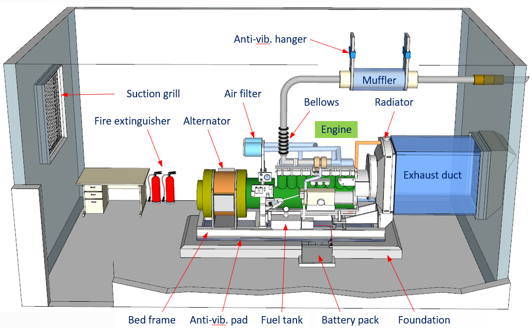
2) The length and width of the foundation should be at least 30 cm greater than the length and width of the generator bed frame.
3) Calculation of foundation depth (D)
W : Generator set Gross Weight (kg)
C : Concrete Density : 2402.8(kg/m³)
B : Foundation Width (m)
L : Foundation Length (m)

|
Safety rules |
Generator users must follow the basic safety rules below to prevent accidents, hazards, and disasters. In particular, the voltage generated by the generator is very dangerous, and contact with it can cause fatal accidents, so be very careful when operating or maintaining the generator. |
||
|
(1) Check point before the running |
Be sure to check the checklist before starting, and take action on any deficiencies. |
1) Check the status of the air supply, ventilation, and combustion gas exhaust facilities. 2) Check the grounding status of the engine body and grounding system. 3) Check the fuel, lubricating oil status and fuel oil leaks. 4) Check the coolant water status and water leaks. 5) Check for obstacles around the engine, alternator and radiator. 6) Check the operating panel parameters and switches operation status. |
|
(2) Cautions while the running |
If there some unusual noise or suspicious phenomenon while running, stop running immediately, analyze the cause, & take an action |
1) Do not add fuel or coolant while running. 2) Never approach the rotating parts while running. 3) Be careful, don't open the radiator cap while running, it can be result in severe burns. 4) Avoid contact with the engine, exhaust pipe, silencer while running as they are heated. |
|
(3) Actions after the running |
When running is finished, first open the main circuit breaker, and wait for a certain time for the engine to be cool down, and then stop the engine. |
1) Even after the engine is stopped, the engine parts and exhaust parts are still heated, so avoid contact it. 2) Once the engine is stopped, recheck for remaining risk factors. 3) Use standard parts for repair equipment that are suitable for the relevant parts. 4) Do not leave flammable substances such as detergents around the engine. 5) Check the battery fluid level on a weekly basis. |
|
Alarmig |
Warnning |
During generator running on, there always hazards such as rotating parts, loud noise, overheated coolant, noxious exhaust fumes, explosive batteries, and high voltage sources. So failures to follow the operating methods and procedures correctly can result in personal injury or shortened equipment life. So the operation always be performed with very careful. |
|
Alert |
If observed any unusual phenomena, such as unstable rotation or unusual smell while running, the generator may malfunction or be damaged, so the generator must always be in alert. |
|
|
Calculation |
In order to operate the generator stably, the generator must always be maintained in optimal condition. To do this, securing the spare parts and regular inspection and maintenance are necessary. |
◐ Operation Methode and Procedure
◎ Manual Operation Procedure
|
Start |
① Mounted type: Turn the key to the start position, and the engine running then turn it back to. ② Separate type: Push the starter switch/button to start the engine. ※ After the starter motor starts, push the starter switch until you hear the generator start. ③ If the engine does not start, wait a while and try again after the starter motor stopped. ※ Caution: Don’t push the starter button for more than 10 seconds, because of motor damage.
|
||
|
Run |
① After starting, check the oil pressure gauge to see if oil pressure is normal. If the oil pressure is not normal, stop the engine immediately, analyze the cause, and restart it. ② Check for any abnormalities in the equipment during running (any leaks, abnormal noises,.) ③ Check the voltmeter and frequency meter to see if they are maintained in the rated state. ④ After checking each instrument and finding no abnormalities, turn on it from the largest load. ⑤ If there is a separate operating panel, start and stop it from the separate operating panel.
|
||
|
Stop |
① When stopping, always release the load first, and stop it when the engine has cooled enough. ② In the case of a separate type, just push the stop button switch. ※ Caution: in case of separate type, always place the key switch at the off (stop) position. |
||
◎ Automatic Operation Procedure
|
Start |
① Set the ‘Manual’ / ‘Automatic’ selection switch to the ‘Automatic’ control position. ② In the case of the button type, push the ‘Automatic’ selection button.
|
||
|
Run |
① In the event of a grid power break, the engine starts automatically, reaches the rated speed, and also establishes the rated voltage. ② When the voltage is lead to the rate, the load circuit breaker is automatically turned on, and the generator's emergency power is supplied to the grid.
|
||
|
Stop |
① When the grid power is recovered during generation, the power is automatically switched to the original grid power within the setting time through the ATS by checking a restored. ② After the power is switched to the grid, the engine is running at no load during the specified time for cooling and then stops. ③ Automatic operation is performed by the grid power breaking signal to start-run-cut-stop, so no required the separate operation activities. |
||
|
Equipment |
Inspection points of generator set |
|
Lubrication |
Oil leakage/filter/level, Hydraulic governor oil level/ /filter, Bypass filter, Engine oil, Hydraulic governor
|
|
Cooling system |
Leakage, Radiator air resistance, Coolant heater status, Hose and pipe condition, Coolant level/antifreeze, Coolant fan belt/hub/drive pulley condition/pump/heat exchanger plug/heater device/coolant system/ radiator system |
|
Suction parts |
Leakage, Filter resistance, Pipe connection status, Crankcase breather, Filter cleaning and replacement |
|
Fuel system |
Leakage, Fuel level, Fuel line connection, Fuel supply pump, Fuel tank sediment, Governor linkage, |
|
Exhaust line |
Leakage, Exhaust resistance, Condensate trap, Exhaust pipe, Turbocharger cap, Silencer |
|
Electrical parts |
Battery charging system, Generator electrolyte/specific gravity, Operation control safety/alarm devices, Field circuit |
|
Alternator |
Abnormal noise/vibration, Base mounting status, Rotating part (engine) fastening status, |
|
Circuit breaker |
Input/output terminal connection status (resistance factor), Lub oil status, Wiring status, Heater operation status |
|
Operation device |
Starter (manual/automatic) switch, Data display, Warning/Alarming lamp |
|
Procedure |
No-load test, Load test (load bank connection), Service tools/zigs |
1) No-load test cycle and operating time
Conducted once or twice a month, and the test time is approximately 5 to 10 minutes depending on the test conditions.
2) Purpose of no-load test:
To discover failures or problems in advance through pre-operation and take measures.
① Engine is stopping for a long time, cylinder wall lub. oil flow down, which can cause wear on the lub. parts when starting.
② Starting battery charging: To prevent engine starting failure due to long-term over discharge of the battery.
3) Generator starting procedure
① With the load circuit breaker open, place the Auto./Manual changeover switch on the op’ panel to the manual position.
② Operate the start switch to run the generator, and record the lead time to rated voltage (within 40 seconds)
4) Function check by no-load test
① Function check is usually conducted every 6 months while running for 5 to 10 minutes.
② During no-load test, the voltage(V) and freq.(F) must be stable within the specified values.(V<+/-2%, F<+5% of rated)
③ Status check items during the no-load test
√ Check the lub. oil pressure, fuel leaks, coolant temp. and circulation/leakage status.
√ Check for abnormal noise, vibration, heat generation, exhaust gas color and smell, and anti-vibration device status.
√ Check the battery charge (check for over-charge/discharge, voltage usually needs to be maintained at 13.2~13.5V)
√ Check the normal operation status by op’ panel meters(voltmeter, ammeter, frequency meter, wattmeter, etc.)
2) Load test items
|
Test item |
Test methode and procedure |
|
Steady-state no-load saturation curve test |
Test the tracking performance by changing of terminal-V at no-load state. |
|
Voltage(V) curve test |
Change the reactive power for each of 25%, 50%, 75%, and 100% power output, measure the field current (If) and terminal voltage (V) at that time, and obtain the reactance value Xd and Xq. |
|
Reactive power limit test |
This test checks the inertia constant (H). When performing the load-cut test, the variation of frequency that changes per unit time depending on the weight or characteristics of the rotor, and the inertia constant (H) can be checked through this slope. this test can be done while operating for approximately 15 minutes at rated power (100%) and rated PF (80%). |
|
Load-cut test |
This is a test to obtain transient and sub-transient reactance value X’d, X’q, X”d, X”q. It can be measured by testing twice in MVR mode and testing once in AVR mode. |
|
No-load AVR step test |
Through the exciter step test (2% units), the generator terminal voltage (V) and field current (If) can be measured, the exciter parameters can be determined, and the generator parameters can be re-verified. |
|
PSS (power stabilization step) test |
Fix the active to 100%, reactive power to 0%, after turn PSS on/off, apply a 2% step signal to the AVR, and test the response status of PSS.. |

AC Generator
Rotating Excitation type Synchronous Generator
Alternator
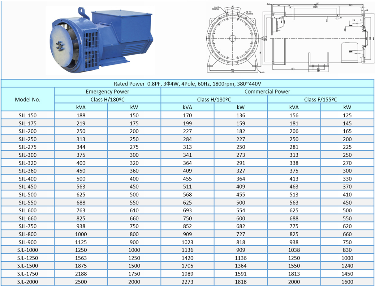
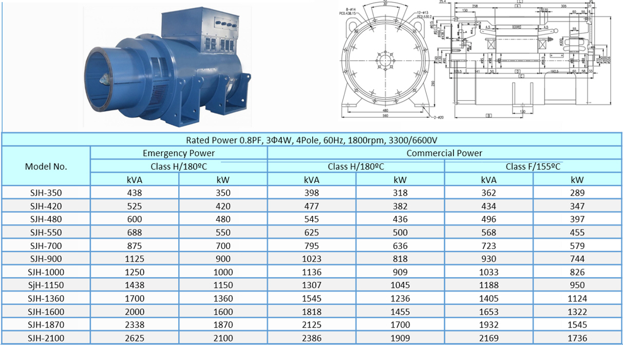
Generator body of Seonjinhitech Co., Ltd. adopts a rotating excitation type synchronous generator. It guarantees high quality, high reliability, and durability to meet customer requirements. In addition, we Seonjinhitech manufactures and produces defect-free products based on perfect design and integrity parts materials, and guarantees a sufficient warranty period and A/S for up to 24 months after delivery.
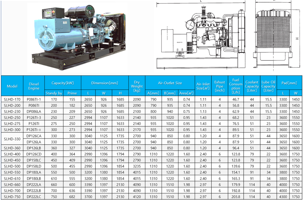
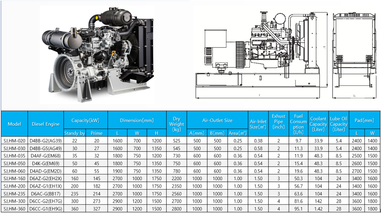
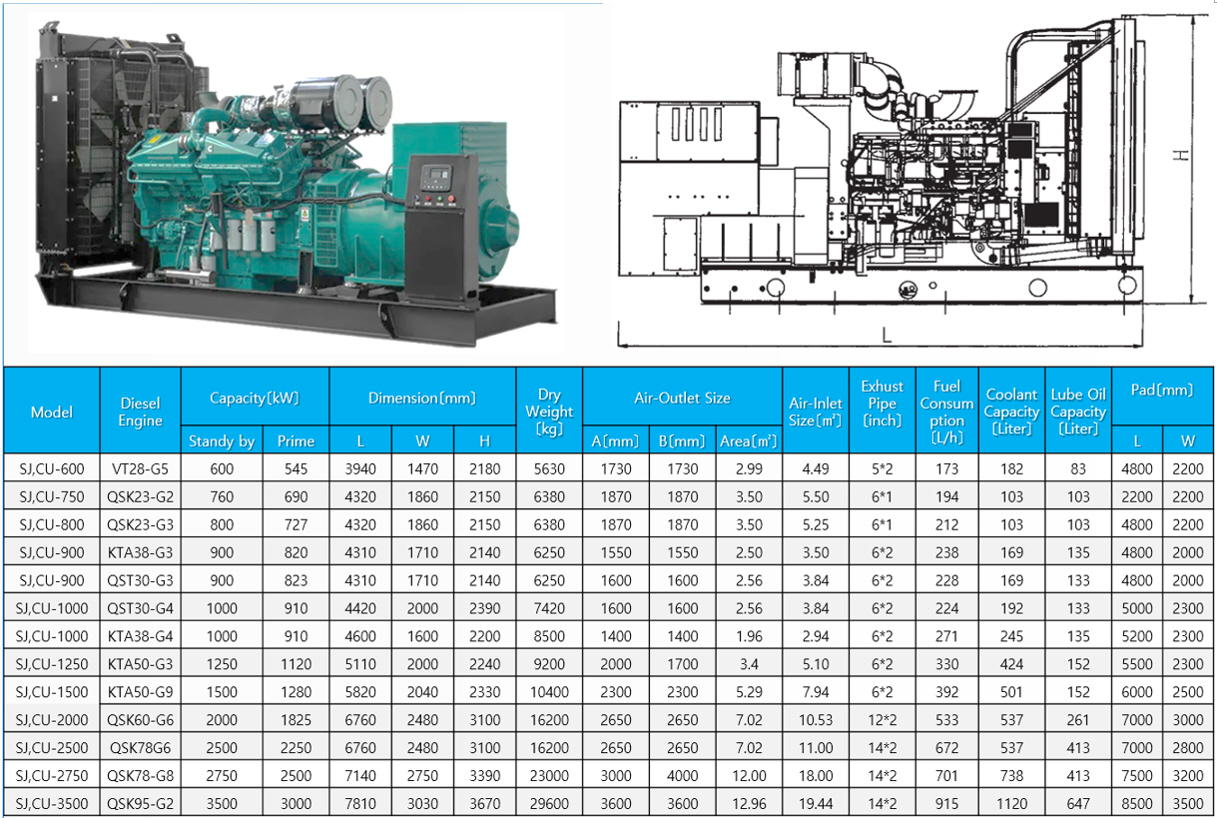
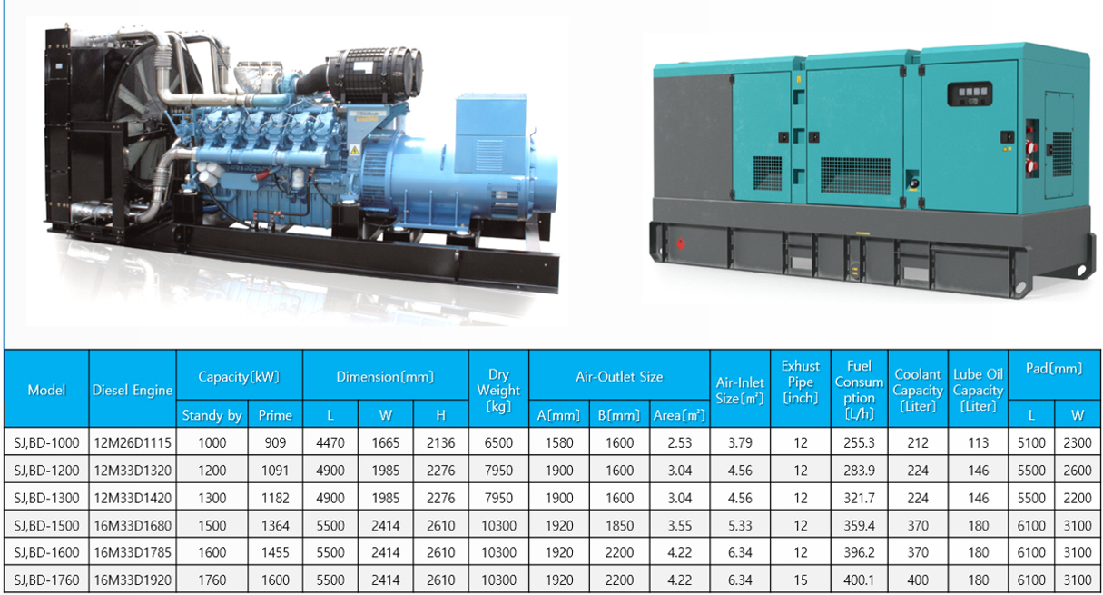
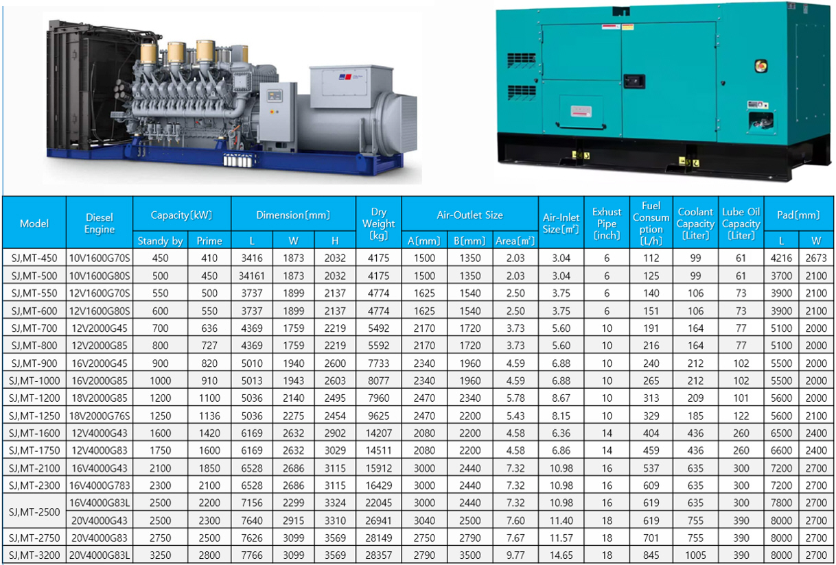
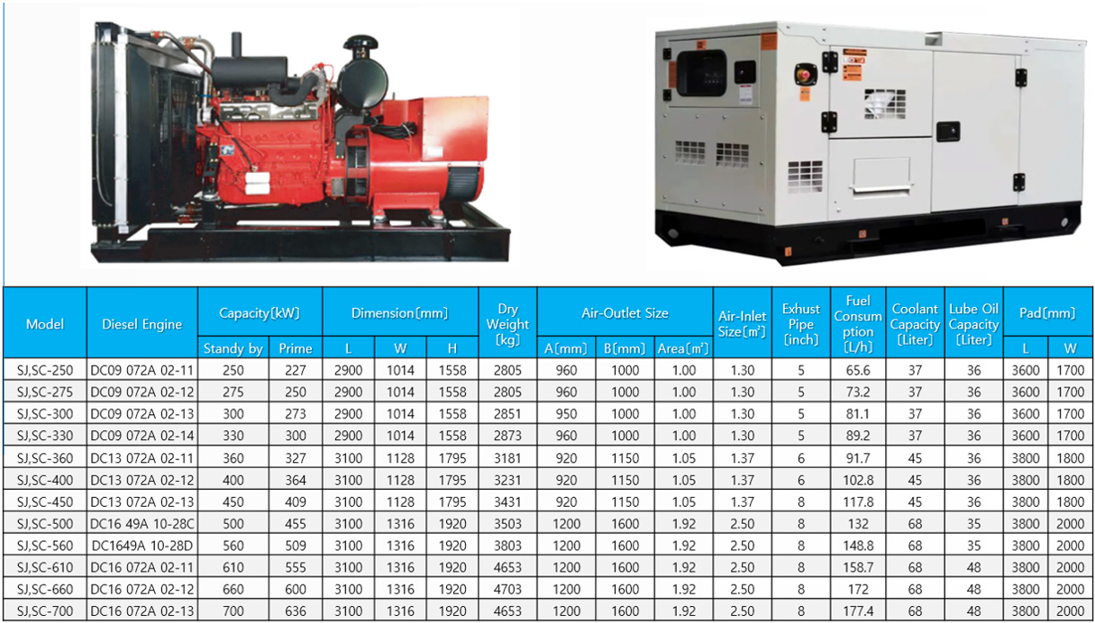
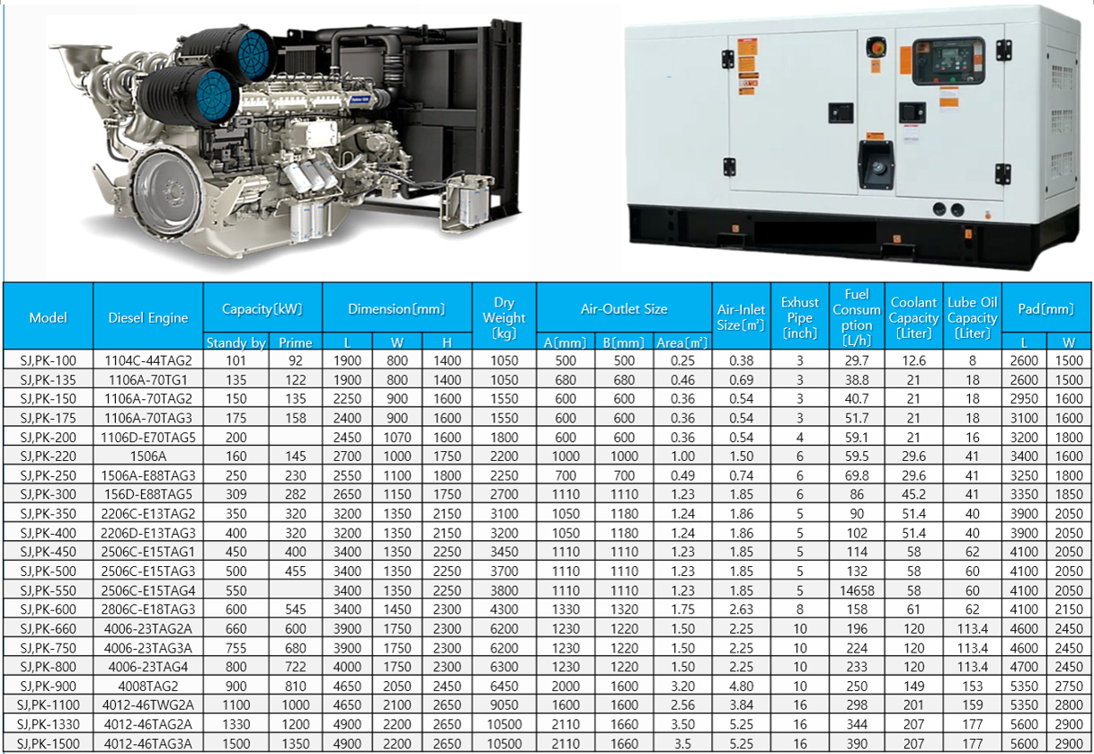
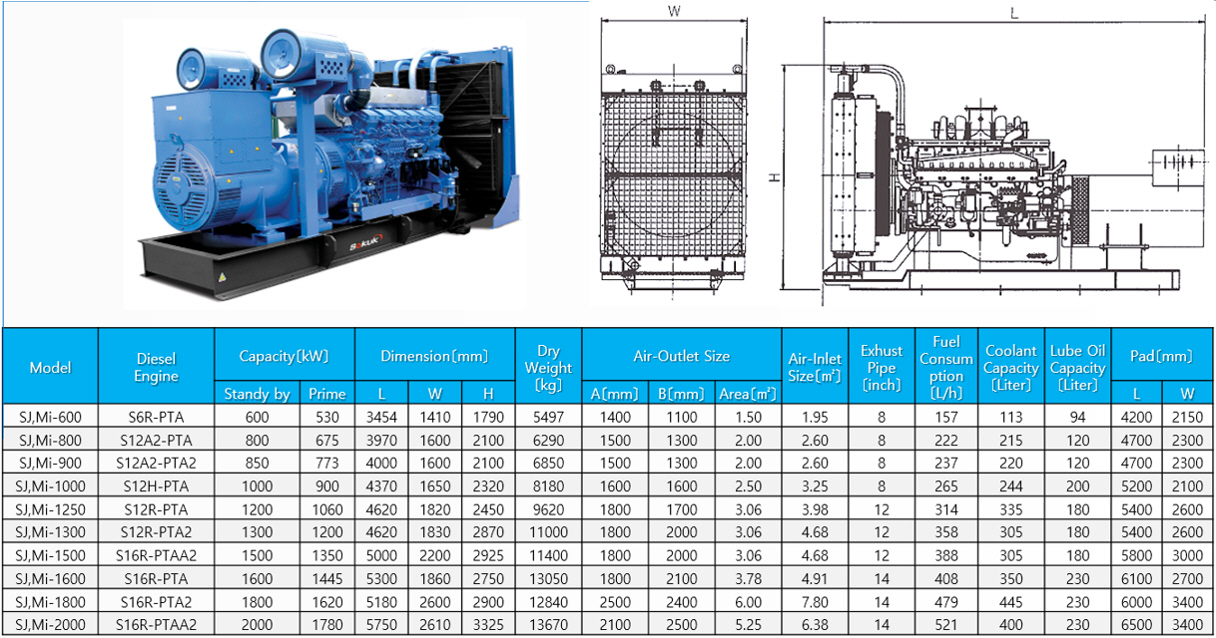
◐ Selection of LV Generator ________________________________________

|
|
 |
 |
 |
 |
 |
 |
 |
 |
 |
 |
|
HD-Hyundai |
Cummins |
Bauduin |
MTU |
Scania |
Perkins |
Mitsubish |
Caterpilla |
Volvo |
MAN |
WeiChai |
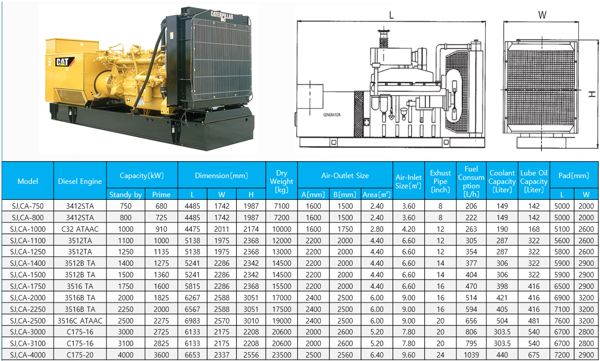
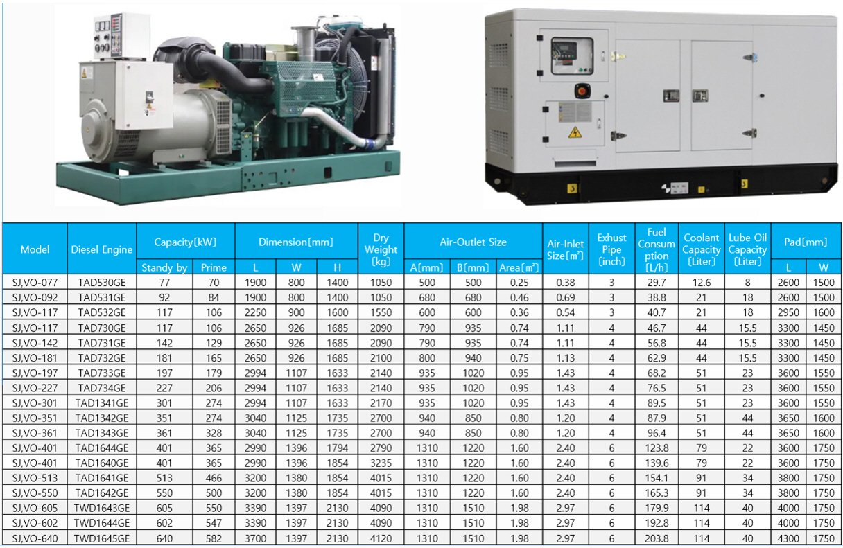
|
|
 |
 |
 |
 |
 |
 |
 |
 |
 |
 |
|
HD-Hyundai |
Cummins |
Bauduin |
MTU |
Scania |
Perkins |
Mitsubish |
Caterpilla |
Volvo |
MAN |
WeiChai |

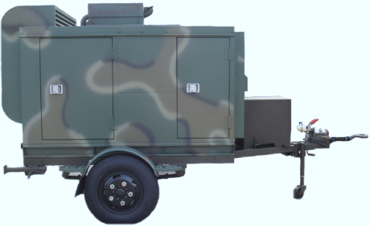
under construction !

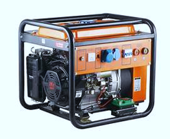
under construction !

***********************************************************************************************************************************************************************************
경기도 화성시 향남읍 발안공단로 4길13 / 대표: 백용호
Tel: +82-31-8059-1387 / Fax: +82-31-8059-1397
E-Mail: sjhtech@seonjinhitech.co.kr
Website: http://seonjinhitech.co.kr


